Scania DI16 XPI. Marine engine en-GB 2 741 685. Operator’s manual - part 5

Fuel system
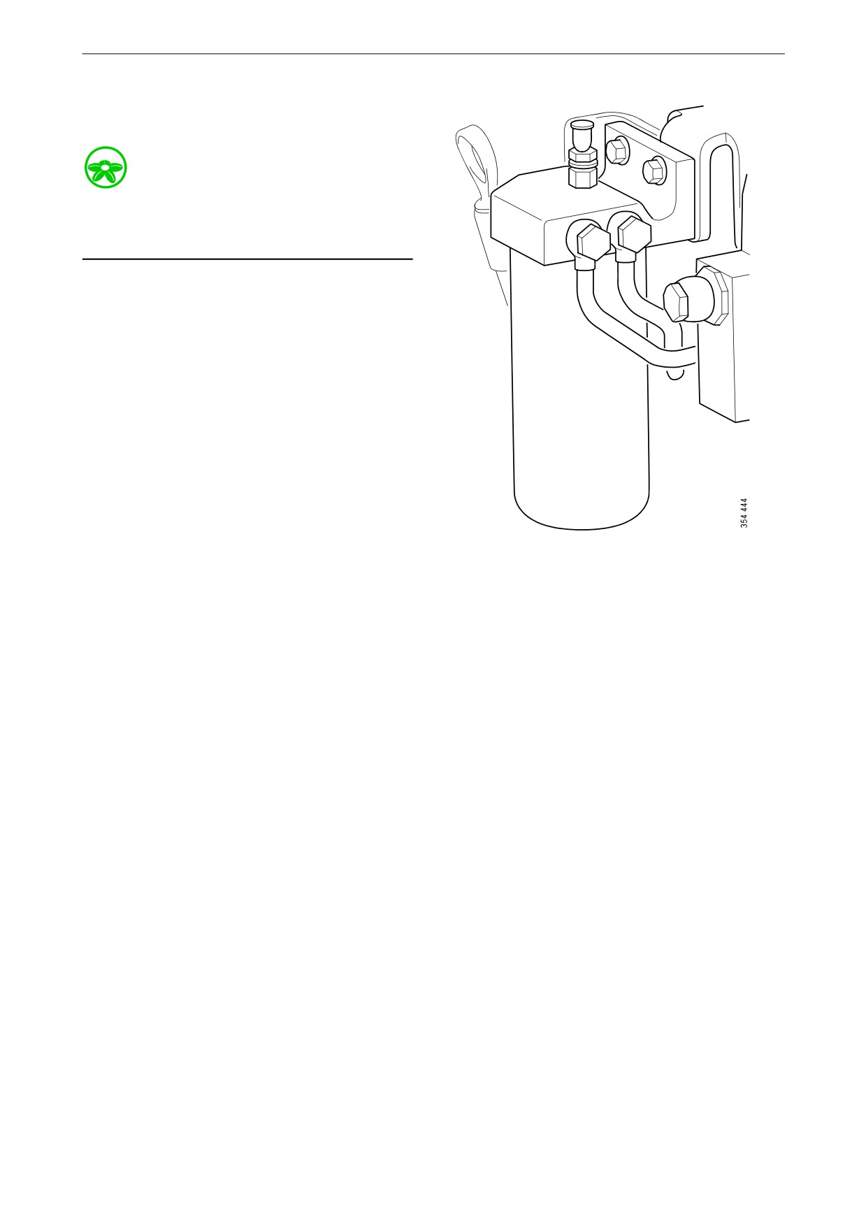
3. Undo the drain plug.
4. Tighten the drain plug when all the water has
emptied.
5. Fill the filter housing with clean fuel.
6. Fit the cover. Tighten the cover screw by
hand.
64

Fuel system
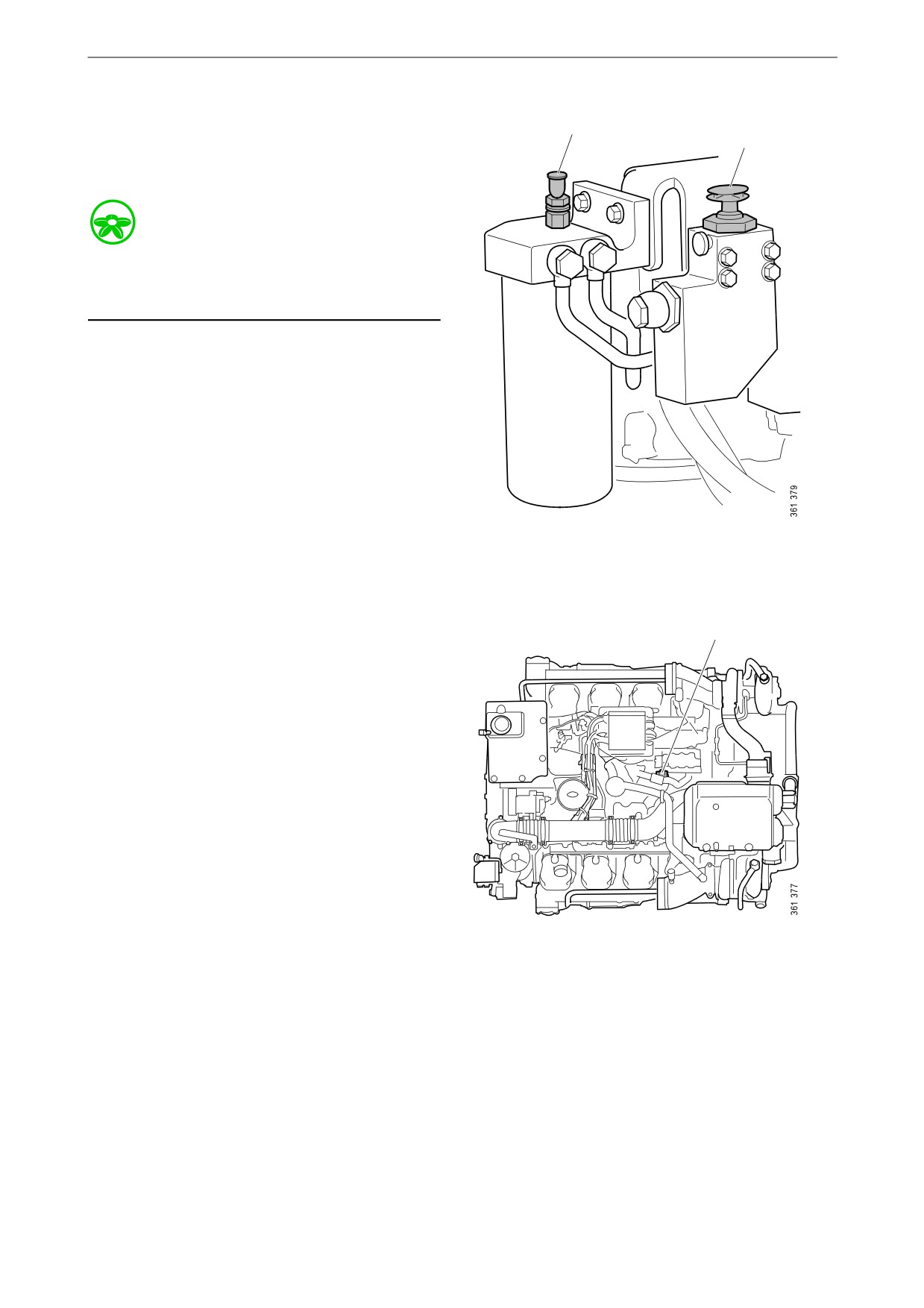
Renewing the commutative,
water separating prefilter
During operation, the rotary control should point
90° towards the filter being used.
Environment
Use a suitable container. The fuel collected must
be disposed of as specified in national and inter-
national laws and regulations.
1. Switch off the filter that needs renewing. The
arrow on the rotary control should point to-
wards the filter that should remain active
during renewal.
WARNING!
Be careful that the valve does not pass the closed
position when the engine is in operation. A
closed position can result in the engine stopping.
In marine applications, the engine stopping rep-
resents a safety hazard.
2. Clean the filter housing externally with a
cloth.
3. Remove the cover from the filter housing.
65

Fuel system
4. Remove the filter and fit the new filter.
5. Renew the O-rings in the cover.
6. Lubricate the O-rings with engine oil.
7. Fill the filter housing with clean fuel.
8. Fit the cover. Tighten the cover screw by
hand.
66

Fuel system
Renewing the reversible fuel
filter, 16 litre marine engine
with XPI
B
A
Tool
Number
Designation
A B
2 002 537
Grease for O-ring
Environment
Since the engine must be running during filter re-
newal, fuel may spill. Use a suitable container.
Collected fuel must be disposed of as specified in
national and international law.
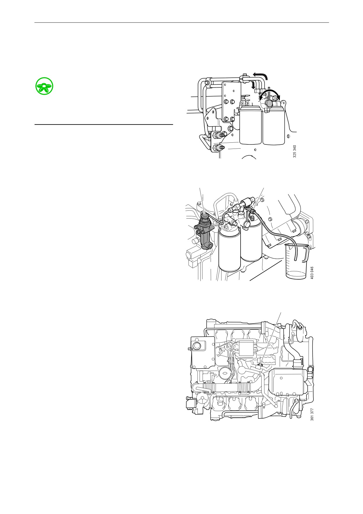
1. Start the engine. During operation, the rotary
control should point 90° towards the filter
being used.
2. Turn the rotary control 90° to the right so that
it points towards filter B. The fuel then flows
through the filter.
3. Connect a clear plastic hose to the bleed nip-
ple sitting above filter A. Place the other end
in a container with a capacity of at least 3.8
litres (1 US gallon).
4. Open the bleed nipple on side A. The re-
maining pressure is released.
5. Clean the exterior of the filter with a cloth.
6. Unscrew the filter.
7. Apply O-ring grease, part number 2 002 537,
to the gasket on the new filter.
8. Screw the filter into place by hand until it
makes contact. Turn screw a further half turn
by hand.
9. Turn the rotary control 90° to the left so that
the rotary control points straight up. Both fil-
ters now run simultaneously.
10. When fuel without air bubbles comes out,
close the bleed nipple. Tightening torque 9
Nm. Because the engine is running, a lot of
fuel will come through the hose.
11. Turn the rotary control 90° to the left so that
the pointer is pointing towards filter A. Filter
B can then be renewed in the same way as fil-
ter A.
67
Fuel system
Renewing the fuel filter
Environment
Use a suitable container. The fuel collected must
be disposed of as specified in national and inter-
national laws and regulations.
1. Clean the exterior of the fuel filter with a
damp cloth.
2. Unscrew the filter.
3. Apply oil to the gasket on the new filter.
4. Screw the filter into place by hand until it
makes contact.
5. Screw a further half turn by hand.
6. Bleed the fuel system according to the in-
structions in the following section.
68
Fuel system
Bleeding the fuel system
2
1
Bleeding the fuel system using a
hand pump
Environment
Use a suitable container. The fuel collected must
be disposed of as specified in national and inter-
national laws and regulations.
1. Screw up the hand pump handle (1).
2. Attach a clear plastic hose to the bleed nipple
on the fuel filter (2). Let the plastic hose drop
into a container that holds at least 5 litres (1.3
US gallons).
3. Open the bleed nipple on the fuel filter.
4. Pump with the hand pump until fuel comes
out.
5. Close the bleed nipple on the fuel filter.
3
6. Attach a clear plastic hose to the bleed nipple
on the high pressure pump (3). Let the plastic
hose drop into a container that holds at least
5 litres (1.3 US gallons).
7. Open the bleed nipple on the high pressure
pump and pump the hand pump until fuel
comes out. It will take around 150 pump
strokes.
8. Close the bleed nipple on the high pressure
pump and screw down the hand pump han-
dle.
9. Start the engine. The engine should be easy
to start.
69

Fuel system
Bleeding the fuel system using a suc-
tion tool
Tool
Designation
Illustration
Suction tool for fuel sys-
tem
Environment
Use a suitable container. The fuel collected must
be disposed of as specified in national and inter-
national laws and regulations.
3
1. Open the bleed nipple on the high pressure
pump (3) and connect the suction tool to it.
2. Hold the suction tool straight and draw out a
full container of fuel.
3. Once the fuel coming out of the hose is free
of air bubbles, then bleeding is complete.
4. Close the bleed nipple on the high pressure
pump. Remove the hose and suction tool.
5. Start the engine and check that no leakage
occurs.
70
Fuel system
Bleeding the fuel system us-
ing a hand pump, 16 litre ma-
rine engine, XPI
Environment
B
A
Use a suitable container. Collected fuel must be
disposed of as specified in national and interna-
tional law.
A B
1. Turn the rotary control so that it is pointing
towards filter B. The fuel will then flow
through the filter.
1
2
2. Unscrew the hand pump handle (1) and con-
nect a transparent plastic hose to the bleed
nipple on the fuel filter (2). Let the plastic
hose drop into a container that holds at least
5 litres (1.3 US gallons).
3. Open the bleed nipple on the fuel filter.
4. Pump with the hand pump until fuel without
bubbles comes out.
5. Close the bleed nipple on the fuel filter.
3
Tightening torque 9 Nm.
6. Attach a clear plastic hose to the bleed nipple
on the high pressure pump (3). Let the plastic
hose drop into a container that holds at least
5 litres (1.3 US gallons).
7. Open the bleed nipple on the high pressure
pump and pump the hand pump until fuel
without bubbles comes out. It will take
around 150 pump strokes.
8. Close the bleed nipple (3 in the illustration)
on the high pressure pump. Tightening
torque 9 Nm. Screw down the hand pump
handle.
71
Fuel system
9. Start the engine. The engine should be easy
to start.
72

Other
Other
Checking the drive belt
IMPORTANT!
Refit the drive belt with the same direction of ro-
tation as it had before removal.
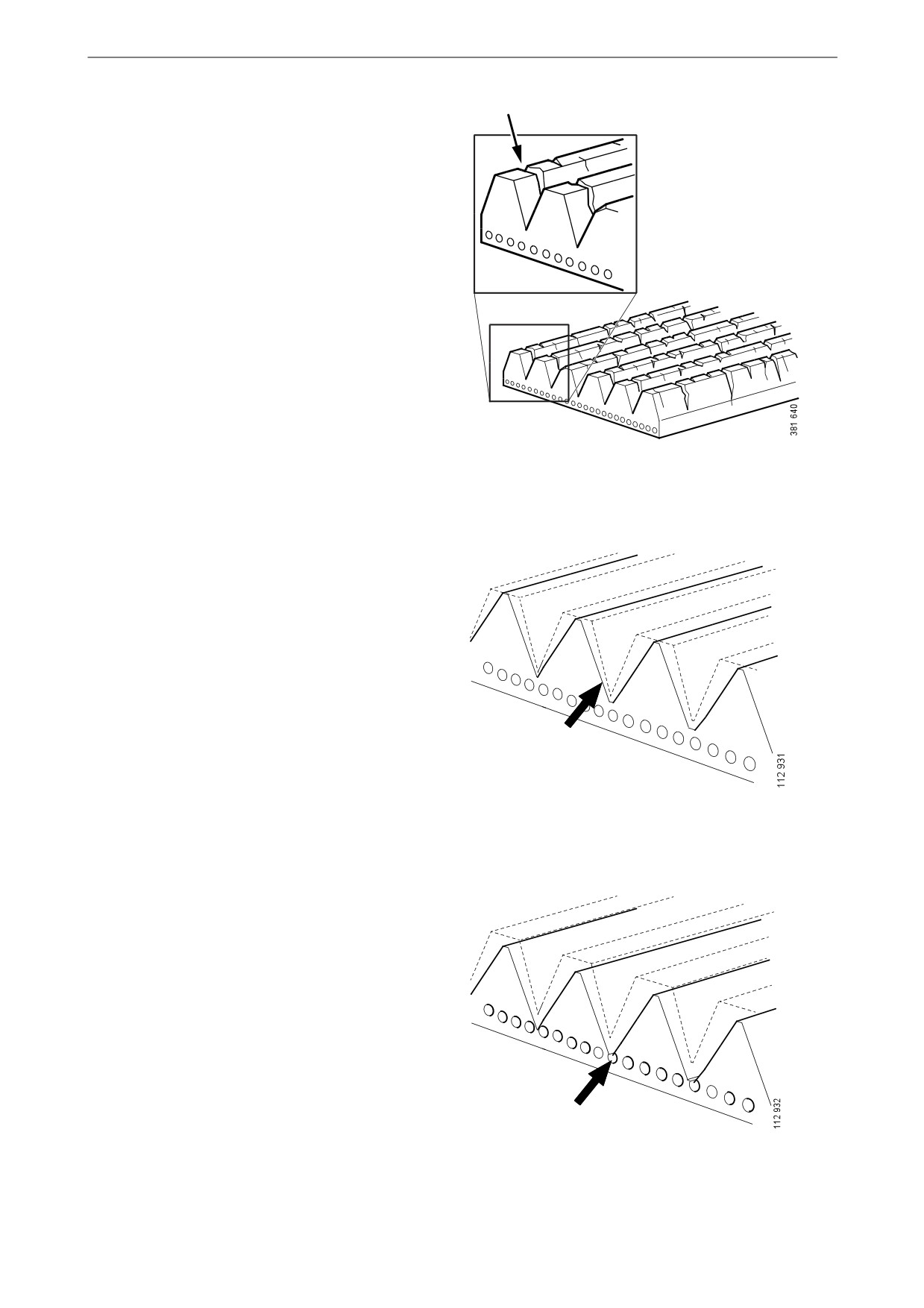
1. Check the drive belt thoroughly, particularly
at the idler rollers.
2. Check the drive belt for cracks. Renew the
drive belt if deep cracks have formed.
Note:
Small and shallow cracks are normal and form
after only a few hours of operation. They do not
mean that the drive belt needs to be renewed.
However, if there are many, deep cracks, the
drive belt must be renewed. See the illustrations.
73
Other
3. Check drive belt wear. Renew the drive belt
if it is too worn. See the illustrations.
74
Other
Checking for leaks
IMPORTANT!
If serious leakage occurs, contact your nearest
Scania workshop.
1. Start the engine.
2. Check for leaks in the lubrication, intake,
cooling, fuel, or exhaust system.
3. Tighten or renew leaking connections.
Check the overflow holes which show
whether the O-rings between the cylinder
liners and crankcase are leaking.
75

Other
Checking and adjusting the
valve clearance
Special tool
Number
Designation
Illustration
99 309
Turning tool for rotating the flywheel from below
2 402 509
Turning tool for rotating the flywheel from above
Other tools
Torque wrench, 0-50 Nm
Waterproof felt-tip pen
Feeler gauge 0.45 and 0.70 mm
Flash light
Mirror
WARNING!
Block the starting device. If the engine starts un-
expectedly, there is a serious risk of injury.
IMPORTANT!
The engine must be cold when the work is car-
ried out.
Remember to remove the turning tool from the
flywheel after adjustment.
Note:
Carry out the working without pausing, so that
no step is overlooked.
Carry out a check and adjustment of the valve
clearances one more time after the first 500 hours
of operation. After this, adjustment according to
the regular interval takes place, which is every
2,000 operational hours.
76
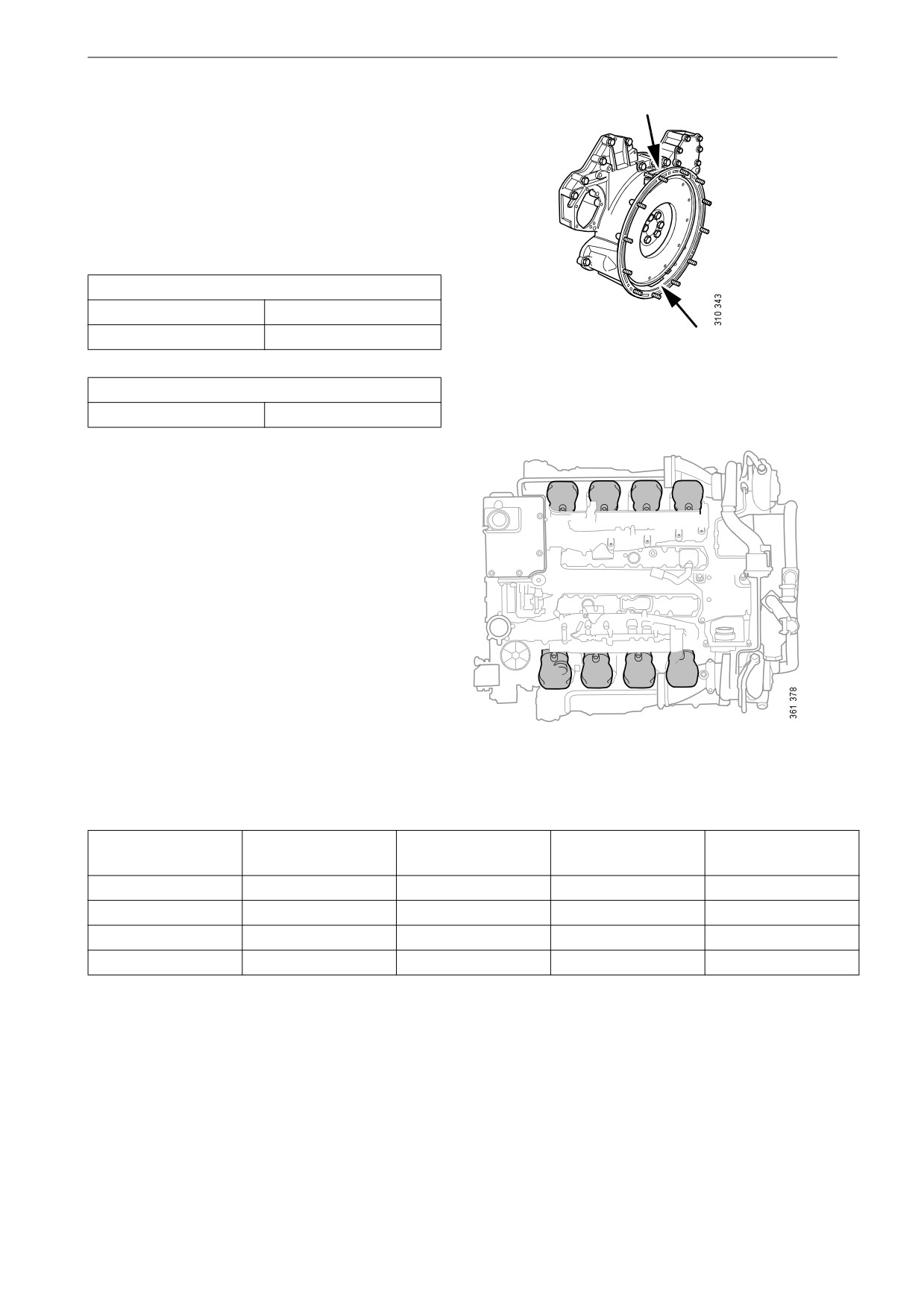
Other
On the flywheel is engraved the reference infor-
mation UP TDC, DOWN TDC and the angle in-
dications listed in the table below. Depending on
the engine installation and type of flywheel
housing, this information is visible in one of the
windows, either furthest up or furthest down on
the flywheel. See illustration.
Valve clearance, specifications
Intake valve
0.45 mm (0.018 in)
Exhaust valve
0.70 mm (0.028 in)
Tightening torque
Lock nut for valves
35 Nm (26 lb/ft)
Adjust valves according to the table below. Fol-
low the respective column depending on whether
1
2
3
4
you are reading the engraving on the flywheel in
the lower or the upper window. Start adjustment
at the top of the table.
5
6
7
8
Reading in the low-
Valve transition on
Adjust intake valve
Adjust exhaust
Reading in the up-
er window
cylinder
on cylinder
valve on cylinder
per window
DOWN TDC(0°)
6
7 and 8
4 and 5
UP TDC(180°)
UP TDC(180°)
7
1 and 5
2 and 6
DOWN TDC(0°)
DOWN TDC(360°)
1
2 and 4
3 and 7
UP TDC(540°)
UP TDC(540°)
4
3 and 6
1 and 8
DOWN TDC(360°)
77
Other
1. Clean the rocker covers and the area around
them.
2. Remove the rocker covers.
3. In order to rotate the flywheel, use a turning
tool compatible with the installation of the
engine, i.e. whether access is from above or
from underneath. Use any specified special
tool or the equivalent from another supplier.
4. Start adjusting one cylinder according to the
table. Rotate the flywheel until the correct
engraving can be read on the flywheel. It
may be necessary to rotate it more than 1 rev-
olution.
Rotate the flywheel in the rotational direc-
tion of the engine, which is clockwise
viewed from the front of the engine and anti-
clockwise viewed from the back of the en-
gine.
During a valve transition, the exhaust valve
(the long arm) is closing at the same time as
the intake valve is opening.
The UP TDC engraving on the flywheel is
now visible in the window furthest up on the
flywheel. The DOWN TDC engraving is vis-
ible in the lower window.
5. Read the table on the previous page to see
which valve to adjust.
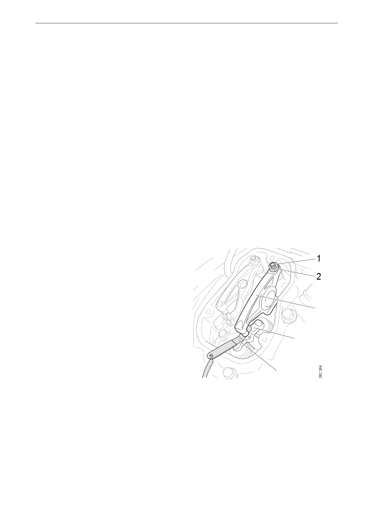
6. Stick the feeler gauge under the pressure pad
of the rocker arm and check the valve clear-
ance.
7. If necessary, adjust the valve clearance by
a) loosening the lock nut on the end of the
3
rocker arm
b) adjusting the valve clearance with the ad-
justing screw
c) tightening the lock nut.
4
8. Mark the rocker arm with the felt-tip pen and
then continue with the next cylinder accord-
ing to the table.
5
78
Quality requirements for fuel
Quality requirements for
fuel
Quality requirements and testing standards for
the most important properties of different types
of fuel are described in the Workshop Manual.
This can be ordered from Scania dealers or di-
rectly from Scania.
Diesel
Properties
The quality of the diesel is very important for the
operation and service life of the engine and the
fuel system, and also for the engine performance.
REQUIREMENT!
The diesel should comply with the requirements
of European standard EN590.
However, Scania accepts larger tolerances of
certain properties. Please see the table below.
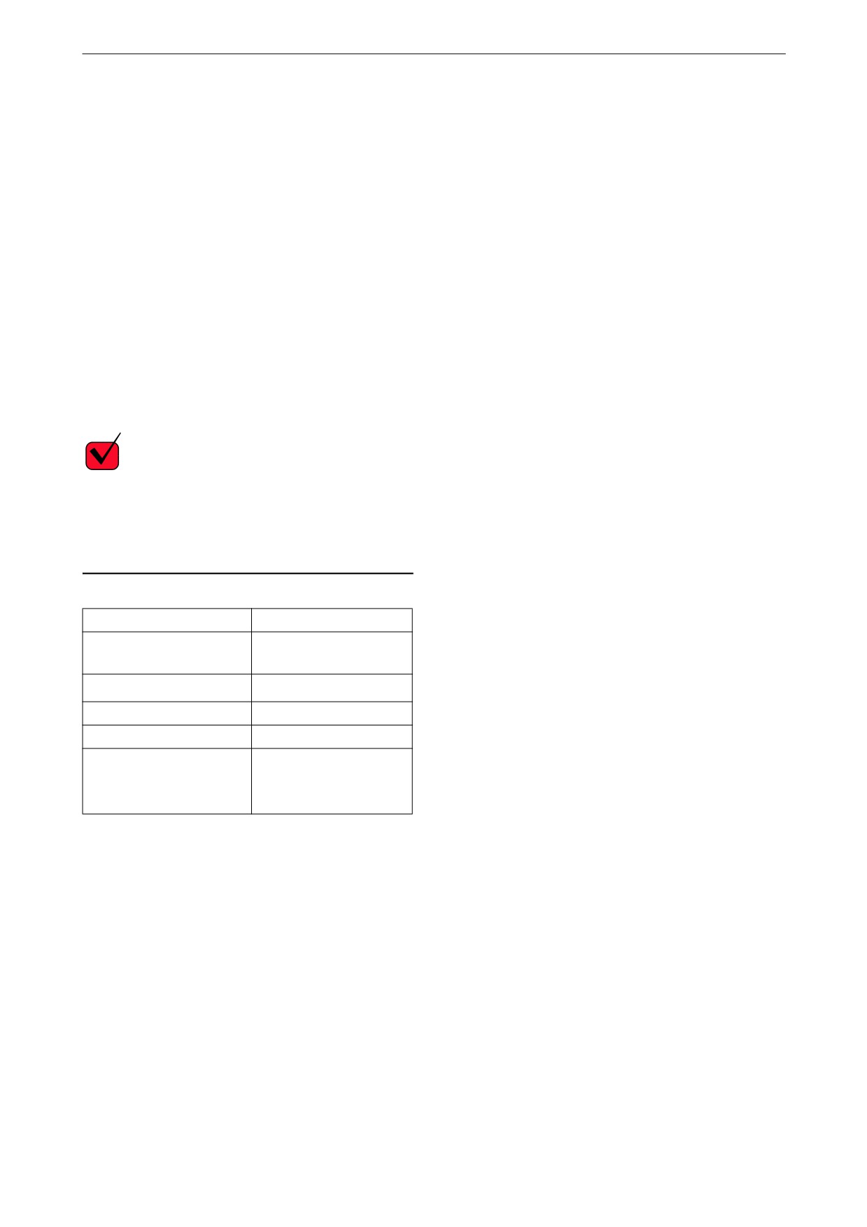
Property
Requirements
Viscosity at 40°C
1.4-4.5 cSt
(104°F)
Density at 15°C (59°F)
0.79-0.87 kg/dm3
Ignitability (CET rating)
minimum 49
Lowest flashpoint
56°C (132°F)
Particulate contamina-
Classification 22/20/17
tion level
according to ISO 4406
79