Scania DI16 XPI. Marine engine en-GB 2 741 685. Operator’s manual - part 3
Air cleaner
Air cleaner
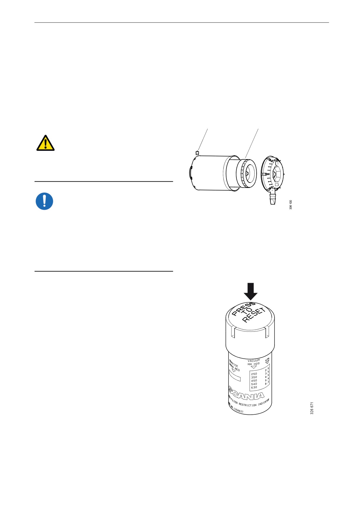
Reading the vacuum indicator
If the indicator's red plunger is fully visible, re-
new the air cleaner filter element following the
instructions below.
Renewing the filter element
A
B
WARNING!
Never start the engine without the air filter being
in place. If you do, this could cause injury and se-
vere engine damage.
IMPORTANT!
Renew the filter element earlier than the mainte-
nance interval if the indicator shows red.
There is always a risk that the filter element will
be damaged when it is cleaned.
The filter element must not be cleaned in water
or be blown clean with compressed air.
1. Remove the cover from the air cleaner.
2. Renew the filter element.
3. Insert a torch into the element and check
from the outside that there are no holes or
cracks in the filter paper.
4. Assemble the air cleaner.
5. Reset the vacuum indicator by pressing the
button.
32
Air cleaner
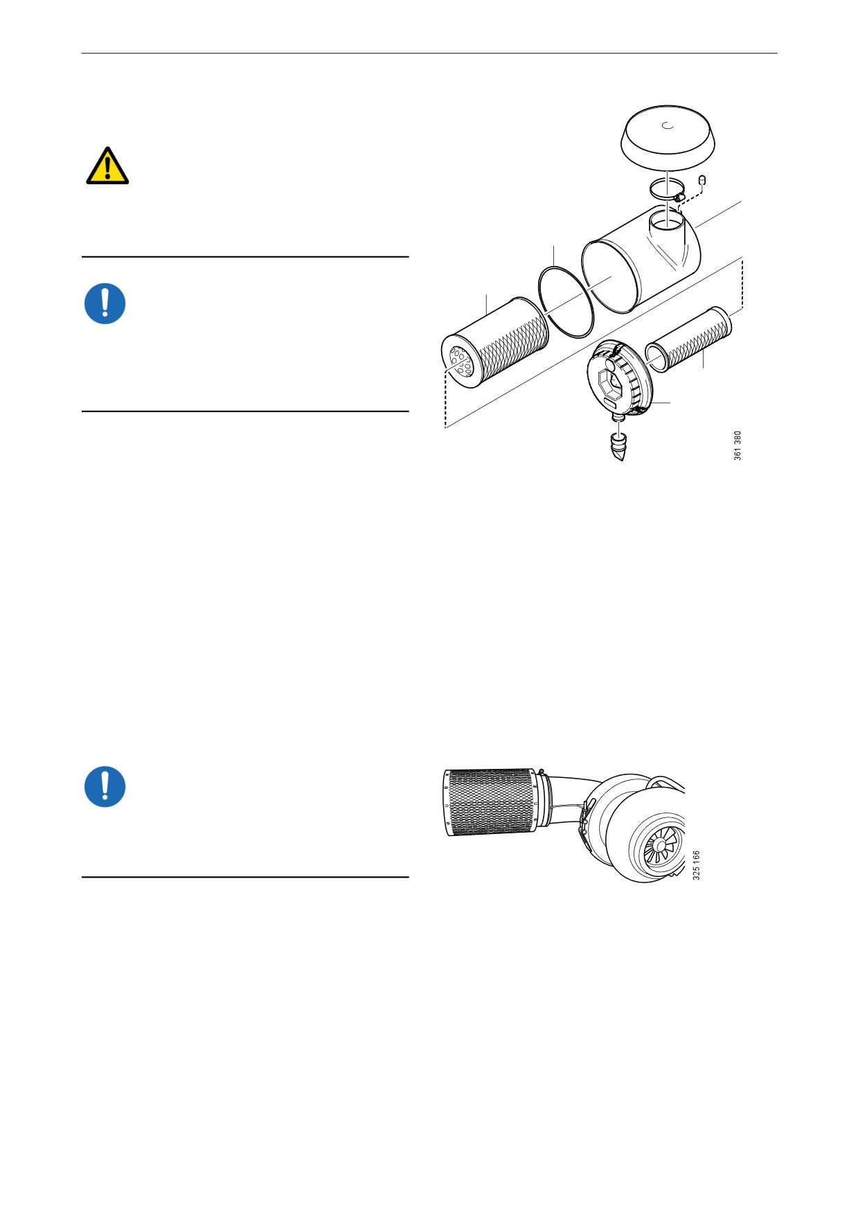
Renewing the safety cartridge
WARNING!
Never start the engine without the air filter being
in place. If you do, this could cause injury and se-
vere engine damage.
4
2
IMPORTANT!
When you renew the safety cartridge, take great
care to ensure that no dirt or other impurities get
into the engine. Do not remove the safety car-
3
tridge unnecessarily.
1
1. Remove the cover from the air cleaner.
2. Remove the filter element.
3. Remove the safety cartridge.
4. Fit a new safety cartridge from Scania.
5. Renew or clean the filter element.
6. Check the condition of the O-ring. Renew
the O-ring if it is damaged or hard.
7. Assemble the air cleaner. Ensure that the O-
ring is not outside the edges.
Renewing an air filter with a
non-renewable element
IMPORTANT!
If the engine has air filters with a non-renewable
Scania element, they should be renewed instead
of cleaned.
33
Cooling system
Cooling system
Coolant
WARNING!
Ethylene glycol can be fatal if ingested and can
cause skin irritation and eye damage.
Note:
The coolant should be changed when the cooling
system is cleaned: every 6,000 hours or at least
every 5 years. See the section Changing the cool-
ant and cleaning the cooling system.
The coolant has several characteristics which are
important for the operation of the cooling sys-
tem:
• Corrosion inhibitor.
• Antifreeze.
• Increases the boiling point.
Scania recommends that the coolant used is a
mixture of water with antifreeze and corrosion
inhibitor (ethylene glycol). The coolant should
always contain 35-55% by volume of antifreeze
and corrosion inhibitor so that the coolant has the
correct properties for the cooling system to work.
34

Cooling system
Coolant resistance to cold
The following example shows coolant properties
with 30 percent by volume of antifreeze and cor-
rosion inhibitor:
• Ice slush starts to form at -16°C (3°F).
• At -30°C (-22°F), there is a risk of cooling
system malfunction.
• There is no risk of damage by freezing with a
minimum antifreeze and corrosion inhibitor
content of 35 percent by volume.
0
10
20
30
40
50
%
0
-10
-16
1
-20
-30
3
2
-40
-50
°C
B
A
The chart depicts coolant properties at different
percents of antifreeze and corrosion inhibitor
concentration by volume.
Curve A: Ice formation starts (ice slush)
Curve B: Damage by freezing occurs
Area 1: Safe range
Area 2: Malfunctions may occur (ice
slush)
Area 3: Risk of damage by freezing
35

Cooling system
Antifreeze and corrosion protection con-
centration table, litres
35% by volume of Scania antifreeze provides
sufficient protection against corrosion.
Example:
• The total volume of the cooling system is 40
litres.
• The measured concentration of ethylene gly-
col is 35% by volume (freezing point -21°C).
According to the table there are 14 litres of
ethylene glycol in the cooling system.
• The required concentration of ethylene glycol
is 45% by volume (freezing point -30°C). Ac-
cording to the table, 18 litres of ethylene gly-
col are required in the cooling system.
• Since there are already 14 litres in the cooling
system, 4 litres of ethylene glycol must be
added to the cooling system (18 - 14 = 4 li-
tres).
Adequate protection against corrosion
Volume of ethylene glycol (%)
35
40
45
50
60
Cooling system volume
Ice slush forms (°C)
-21
-24
-30
-38
-50
(litres)
11
12
14
15
18
30
14
16
18
20
24
40
18
20
23
25
30
50
21
24
27
30
36
60
25
28
32
35
42
70
28
32
36
40
48
80
32
36
41
45
54
90
35
40
45
50
60
100
39
44
50
55
66
110
Volume of ethylene glycol (litres)
42
48
54
60
72
120
46
52
59
65
78
130
49
56
63
70
84
140
53
60
68
75
90
150
56
64
72
80
96
160
60
68
77
85
102
170
63
72
81
90
108
180
67
76
86
95
114
190
70
80
90
100
120
200
36

Cooling system
Antifreeze and corrosion protection con-
centration table, US gallons
35% by volume of Scania antifreeze provides
sufficient protection against corrosion.
Example:
• The total volume of the cooling system is
10.6 US gallons.
• The measured concentration of ethylene gly-
col is 35% by volume (freezing point -6 °F).
According to the table there are
3.7 US gallons of ethylene glycol in the cool-
ing system.
• The required concentration of ethylene glycol
is 45% by volume (freezing point -22 °F). Ac-
cording to the table, 4.8 US gallons of ethyl-
ene glycol are required in the cooling system.
• Since the cooling system already contains
3.7 US gallons, fill another 1.1 US gallons of
ethylene glycol in the cooling system (4.8 -
3.7 = 1.1 US gallons).
Adequate protection against corrosion
Volume of ethylene glycol (%)
35
40
45
50
60
Cooling system volume
Ice slush forms (°F)
-6
-11
-22
-36
-58
(US gallons)
2.9
3.2
3.7
4
4.8
7.9
3.7
4.2
4.8
5.3
6.3
10.6
4.8
5.3
6.1
6.6
7.9
13.2
5.5
6.3
7.1
7.9
9.5
15.9
6.6
7.4
8.5
9.2
11.1
18.5
7.4
8.5
9.5
10.6
12.7
21.1
8.5
9.5
10.8
11.9
14.3
23.8
9.2
10.6
11.9
13.2
15.9
26.4
Volume of ethylene glycol (US gal-
10.3
11.6
13.2
14.5
17.4
29.1
lons)
11.1
12.7
14.3
15.9
19
31.7
12.2
13.7
15.6
17.2
20.6
34.3
12.9
14.8
16.6
18.5
22.2
37
14
15.9
18
19.8
23.8
39.6
14.8
16.9
19
21.1
25.4
42.3
15.9
18
20.3
22.5
26.9
44.9
16.6
19
21.4
23.8
28.5
47.6
17.7
20.1
22.7
25.1
30.1
50.2
18.5
21.1
23.8
26.4
31.7
52.8
37

Cooling system
Antifreeze and corrosion protection
products
Only Scania coolant or other products that Scan-
ia has tested to provide proper antifreeze and cor-
rosion protection, may be used in Scania
engines. Products that do not satisfy the require-
ments for use in a Scania engine can result in
faults in and damage to the cooling system. This
can lead to the invalidation of Scania's warranty
for faults and damage caused by the use of inap-
propriate coolant.
The antifreeze and corrosion protection products
used in Scania engines should be of the ethylene
glycol type.
Below is a list of Scania antifreeze and corrosion
protection products.
Scania concentrate
Coolant with antifreeze and corrosion inhibitor
in the form of a concentrate.
Part no.
Volume
Volume
litres
US gallons
1 894 323
5
1.3
1 894 324
20
5.3
1 894 325
210
55
1 894 326
1,000
264
Scania Ready Mix
Coolant with antifreeze and corrosion inhibitor
Ready Mix 50/50.
Part no.
Volume
Volume
litres
US gallons
1 921 955
5
1.3
1 921 956
20
5.3
1 921 957
210
55
1 896 695
1,000
264
38
Cooling system
Checking coolant level
WARNING!
Do not open the coolant filler cap in the expan-
sion tank if the engine is hot. Hot coolant and
steam may spray out and cause burns.
If the cap has to be opened do it slowly to release
the pressure before removing the cap. Wear pro-
tective gloves as the coolant is still very hot.
IMPORTANT!
It is not permissible to top up large amounts of
coolant via the expansion tank. Filling via the ex-
pansion tank leads to air locks in the cooling sys-
tem which can lead to e.g. cavitation damage to
the coolant pump shaft seal. If a large amount of
coolant needs to be added, follow the instruc-
tions in the section Filling coolant.
Only pour pre-mixed coolant into the cooling
system.
1. Check the coolant level through the sight
glass on the expansion tank.
2. Top up with coolant as necessary.
39

Cooling system
Checking the coolant's anti-
freeze and corrosion protec-
tion
Tool
Designation
Illustration
Refractometer
IMPORTANT!
Use only pure fresh water that is free from parti-
cles, sludge and other impurities.
1. Pour a small amount of coolant into a con-
tainer and check that the coolant is pure and
clear.
2. Change the coolant if it is contaminated or
cloudy.
3. Measure the antifreeze content with a refrac-
tometer.
The following rules apply to ethylene glycol-
based coolant:
• The antifreeze and corrosion inhibitor content
must be minimum 35 percent by volume for
corrosion protection to be sufficient.
• An antifreeze and corrosion inhibitor content
greater than 55 percent by volume impairs the
ability to protect against frost.
• If ice forms in the coolant, there are disrup-
tions initially, but there is no immediate risk
of damage. The engine should not be subject-
ed to heavy loads when ice starts to form.
40
Cooling system
Checking sacrificial anodes
1. Drain the sea water circuit. See the section
Draining the sea water circuit.
2. Check the sacrificial anodes and scrape off
all loose material from them.
3. Renew the sacrificial anode if less than half
of it is left. A new sacrificial anode is 60 mm
long with a diameter of 17 mm.
4. Renew the gasket when fitting.
5. If the sacrificial anodes are very corroded,
the inspection intervals must be reduced.
Checking the sea water pump
impeller
1. Drain the sea water circuit. See the section
Draining the sea water circuit.
2. Check that the vanes of the impeller are not
heavily splintered or damaged.
41

Cooling system
Renewing the sea water pump impel-
ler
Special tool
Number
Designation
Illustration
2 443 680
Puller
Note:
If the impeller must be renewed frequently, the
cleaning of the sea water needs to be improved.
There should be a spare impeller on board.
The impeller can be deformed during extended
periods of inactivity. Renew the impeller before
starting or remove the impeller before longer pe-
riods of stoppage.
1. Thread the puller stud into the rubber impel-
ler using an internal hexagon key until the
stud reaches the bottom.
Note:
Note the direction of rotation of the impeller
vanes.
2. Screw the puller into the rubber impeller us-
ing the handle until it reaches the stud. Then
continue to screw until the impeller comes
loose.
3. Unscrew the stud.
IMPORTANT!
Check that the direction of rotation of the impel-
ler vanes is the same as during removal.
4. Lubricate the impeller with pump grease and
then fit it using a rubber mallet.
5. Fit the sea water pump cover. Tightening
torque 7.5 Nm (5.5 lb/ft).
42

Cooling system
Changing the coolant and
cleaning the cooling system
Draining coolant
Special tool
Number, designation
2 443 679, coolant
pump
WARNING!
Do not open the coolant filler cap in the expan-
sion tank if the engine is hot. Hot coolant and
steam may spray out and cause burns. If the cap
has to be opened do it slowly to release the pres-
sure before removing the cap.
Use protective gloves as coolant can cause irrita-
tion if it comes in contact with the skin. Hot cool-
ant can also cause scalding.
Environment
Use a suitable container. Used coolant must be
disposed of as specified in national and interna-
tional laws and regulations.
1. Open the expansion tank cap.
2. Position the hose from the coolant pump in
an empty container.
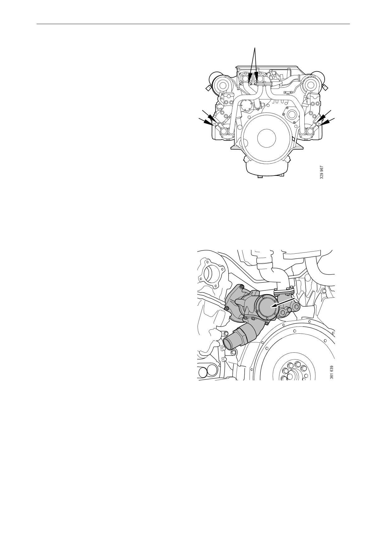
3. Connect the pump to the draining nipple in
the cylinder block. See illustration.
4. Connect the pump's 2 cable terminals to the
battery's negative and positive terminal.
Make sure that the drainage starts. If the
drainage does not start: Change the position
of the cable terminals.
5. Repeat the procedure at the cooling system's
lowest drainage point. The location of the
lowest drainage point on the engine may dif-
fer depending on engine application.
43

Cooling system
Draining the sea water circuit
1. Close the bottom valve on the sea water inlet
and remove the connection pipe on the outlet
from heat exchanger (1).
1
2. Remove the cover from the sea water pump
to completely drain the pump (2).
2
The lowest point in the sea water circuit may be
3
at different points, but it is usually in the sea wa-
ter pump intake (3).
IMPORTANT!
Plug the connections to prevent dirt ingress into
the engine.
Removing the charge air cooler
When the charge air cooler core needs cleaning,
the charge air cooler must be removed if there is
no space behind it to take out the core.
1. Make sure that the cooling system is com-
pletely drained as described in the previous
section.
2. Unscrew and remove the catwalk, protective
plate and the protective casing.
44
Cooling system
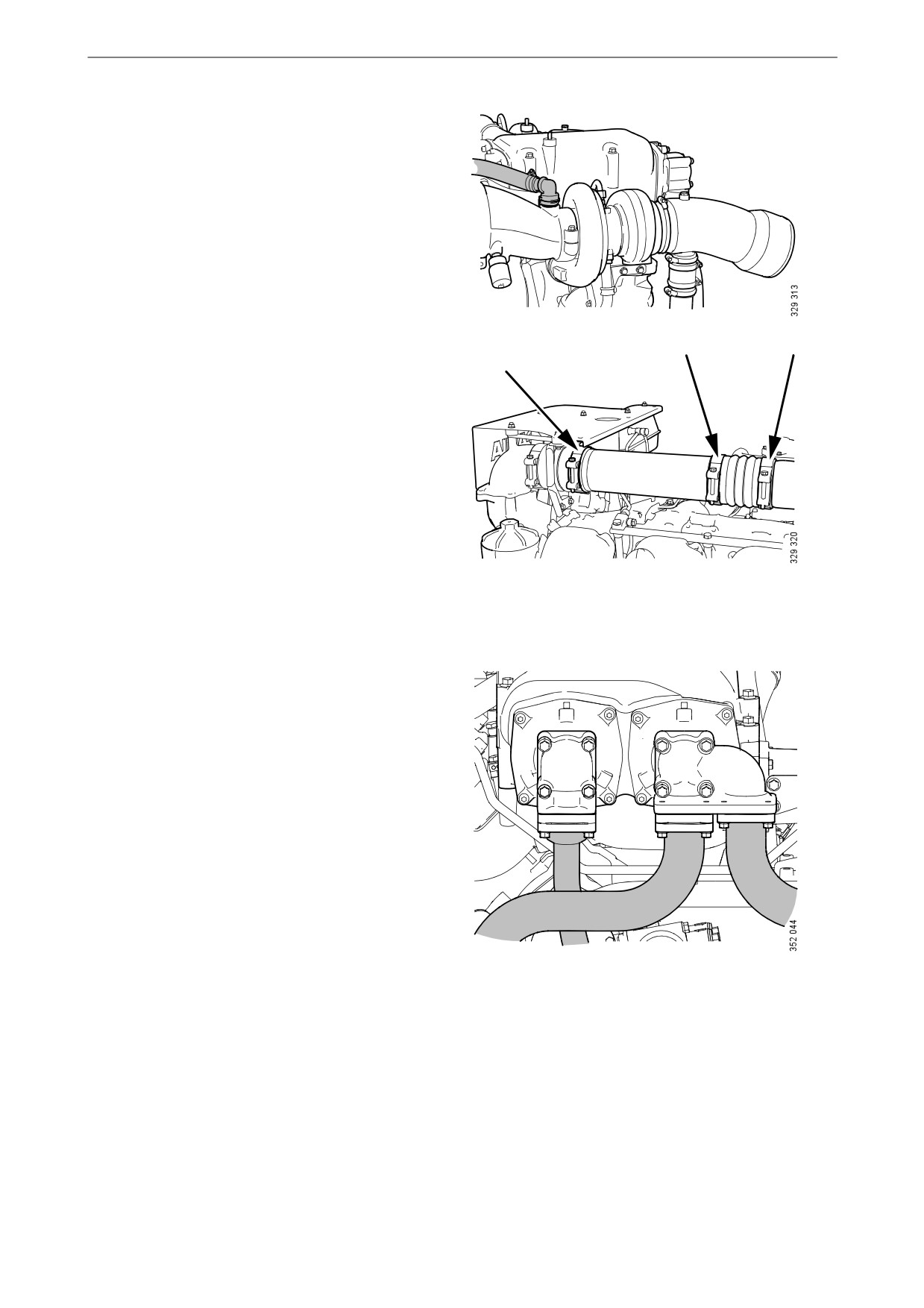
3. On the left-hand turbocharger, remove the
hose between the oil mist separator and the
air filter flange. Use a screwdriver to pull out
the lock.
4. Loosen and remove the hose clamps for the
charge air pipe.
5. Remove all sea water pipes to and from the
charge air cooler.
45
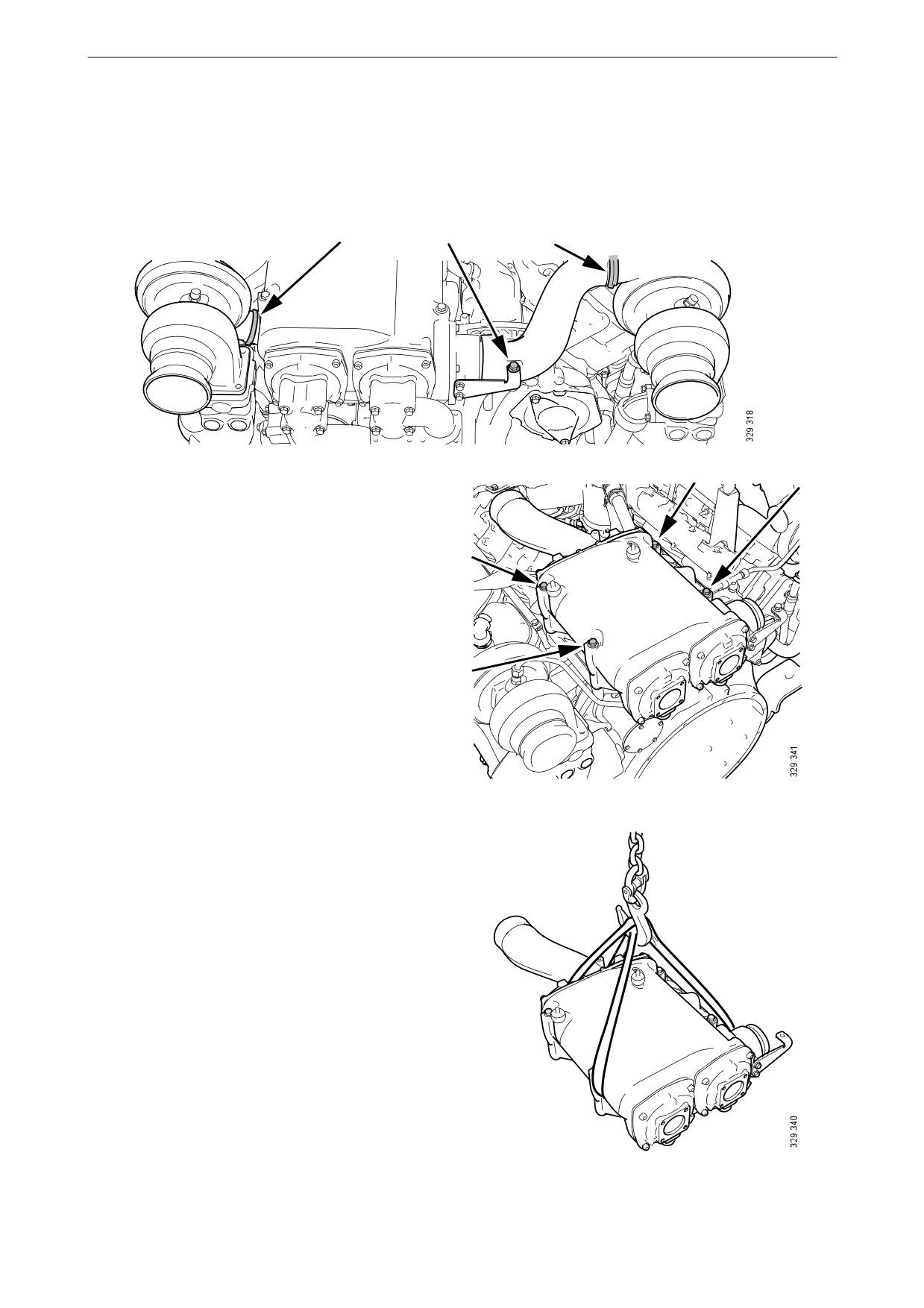
Cooling system
6. Right-hand turbocharger: Remove the V-
clamp and the screw for the bracket. Remove
the charge air pipe.
7. Left-hand turbocharger: Remove the V-
clamp and carefully turn the charge air pipe
during removal.
8. Remove the screws securing the charge air
cooler.
9. Lift out the charge air cooler.
46
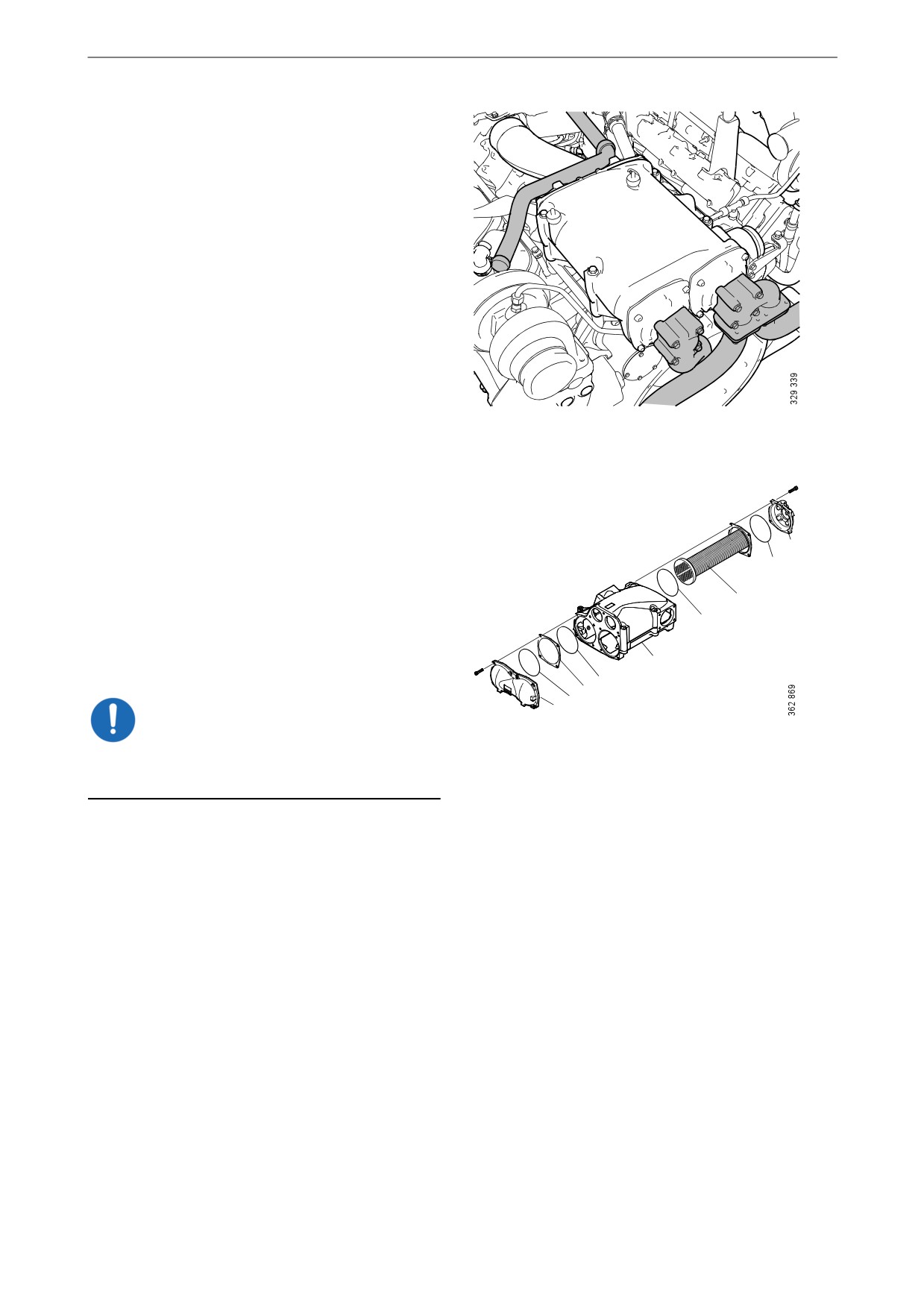
Cooling system
Cleaning the charge air cooler
The charge air cooler must be removed if there is
no space behind it to take out the cooler cores.
See previous section.
1. Remove the sea water pipes to and from the
charge air cooler. Remove flanges and
charge air pipe from the charge air cooler.
Remove the old gaskets and scrape off any
gasket residue.
2. Remove the screws on the charge air cooler
covers (1) and remove the covers. Mark the
covers so that you can put them back on the
correct side.
1
3. Press in the cooler core (5) slightly on one
2
side and pull it out from the other side.
5
4. Clean the cooler core on the outside with par-
2
affin-based engine detergent. Remove any
internal deposits using a round rod. Renew
4
the cooler core if it is damaged.
2
3
2
1
IMPORTANT!
Do not use caustic soda as this could damage the
aluminium.
5. Renew damaged or hard O-rings (2).
6. Assemble the charge air cooler. Tighten the
M8 screws on the cover to 15 Nm (11 lb-ft).
47