Scania DI16 XPI. Marine engine en-GB 2 741 685. Operator’s manual - part 2
Starting and running
Starting at low temperatures
Limp home mode
Take the local environmental requirements into
If there is a fault in the normal throttle opening or
account. Use a fuel heater and engine heater to
if CAN communication is interrupted, the fol-
avoid starting problems and white smoke.
lowing emergency operation option is provided:
Scania recommends that an engine heater should
A CAN fault or throttle opening fault in an all-
be used if the engine will be used at temperatures
speed engine (both signal and idling switch):
below -10°C (14°F).
• The throttle opening value is 0% and the en-
A low engine speed and a moderate load on a
gine is running at normal idling speed.
cold engine limits white smoke, gives better
• The throttle opening value is 0% and the en-
combustion and warms up the engine more
gine is running at raised idling speed (750
quickly than warming it up with no load.
rpm) if this function is activated.
Avoid running it longer than necessary at idling
Throttle opening fault, but the idling switch is
speed.
working:
• The throttle opening value can be increased
slowly between 0 and 50% by using the idling
Running
switch.
Check instruments and warning lamps at regular
CAN fault:
intervals.
• The engine is switched off if the shutdown
Engine speed range
function is activated.
The engine operating speed range is between low
idling and the nominal engine speed. The nomi-
nal engine speed is indicated on the engine data
Driving at high altitude
plate. Low idling can be set between 500 and
1,050 rpm.
When driving at high altitudes engine power is
reduced automatically due to the lower oxygen
content in the air. It is then not possible to run the
engine at maximum power.
The engine must not be run at an altitude of more
than 1,000 metres. Contact Scania if the operat-
ing conditions deviate from these.
16
Starting and running
Coolant temperature
Oil pressure
Normal oil pressure during operation is 3-6 bar
IMPORTANT!
(43.5-87 psi). The lowest permitted oil pressure
when idling is 0.7 bar (10.2 psi).
An excessive coolant temperature can cause en-
The engine management system issues an alarm
gine damage.
at the following levels:
• At an engine speed below 1,000 rpm and an
Normal coolant temperature during operation is
oil pressure below 0.7 bar (10.2 psi).
approximately 94°C (200°F).
• At an engine speed above 1,000 rpm and an
The alarm levels are set in the engine control
oil pressure below 2.5 bar (36.3 psi) for
unit. The default setting for the lowest and high-
longer than 3 seconds.
est limit values for high coolant temperature are
95 °C (203 °F) and 105°C (221°F) respectively.
The incorrect oil pressure alarm has the follow-
ing functions:
The high coolant temperature alarm has the fol-
lowing functions:
• Alarm only.
• Alarm and torque reduction by 30%.
• Alarm only.
• Alarm and engine shutdown.
• Alarm and torque reduction at the lowest lim-
it value.
• Alarm and engine shutdown override control.
• Alarm at the lowest limit value and engine
Note:
shutdown at the highest limit value.
High oil pressure (above 6 bar/87 psi) is normal
• Alarm, torque reduction at the lowest limit
if the engine is cold when started.
value and engine shutdown at the highest lim-
it value.
• Alarm at the lowest limit value and engine
Charging indicator lamp
shutdown at the highest limit value with the
possibility of engine shutdown override con-
If the lamp comes on during operation: Check
trol.
and adjust the alternator drive belt according to
the instructions in the section Checking the drive
• Alarm, torque reduction at the lowest limit
belt.
value and engine shutdown at the highest lim-
it value, with the possibility of engine shut-
If the charging indicator lamp is still on, this
down override control.
could be due to an alternator fault or a fault in the
electrical system.
If run for extended periods under an extremely
light load, the engine may have difficulty in
Belt transmission
maintaining the coolant temperature. At an in-
When the belt transmission is new, it may make
creased load the coolant temperature rises to the
a squeaking noise when running. This noise is
normal value.
normal and disappears after 50-100 hours of op-
eration. The noise does not affect the service life
of the belt transmission.
17
Starting and running
Engine shutdown
Checks after running
IMPORTANT!
WARNING!
There is risk of post boiling and of damage to the
Block the starting device when working on the
turbocharger if the engine is switched off with-
engine. If the engine starts unexpectedly, there is
out cooling. The power must not be switched off
a serious risk of injury.
before the engine has stopped.
There is always a risk of sustaining burns when
an engine is hot. Particularly hot parts are engine
manifolds, turbochargers, oil sumps, as well as
Note:
hot coolant and oil in pipes and hoses.
The battery voltage must remain on for a few
seconds after the 15 voltage is switched off so
that the control units can store the values and
switch to standby mode.
IMPORTANT!
10 prohibited engine shutdowns will cause a
Check the coolant level following the first start.
torque reduction (70% of fuel quantity). Reset
Top up with coolant as necessary.
the engine by switching it off correctly once.
1. Check that the power supply has been cut.
1. Run the engine without a load for a few min-
utes if it has been run continuously with a
2. Top up the fuel tank. Make sure that the filler
heavy load.
cap and the area round the filler opening are
clean to avoid contamination of the fuel.
2. Switch off the engine.
3. If there is a risk of freezing, the cooling sys-
tem must contain enough glycol. See the sec-
tion Coolant resistance to cold.
4. If the temperature is below 0°C (32°F): Pre-
pare for the next start by connecting the en-
gine heater (if fitted).
18

Maintenance
Maintenance
IMPORTANT!
The maintenance programme covers a number of
points that are divided into the following sec-
On delivery a Scania engine is optimised for its
tions:
application. However, regular maintenance is
necessary to:
• Lubrication system.
•
prevent unplanned stops
• Air cleaner.
•
extend the service life of the engine
• Cooling system.
•
maximise the long-term emission perfor-
• Fuel system.
mance of the engine
• Other.
•
give the best possible operating economy.
WARNING!
Block the starting device when working on the
engine. If the engine starts unexpectedly, there is
a serious risk of injury.
There is always a risk of sustaining burns when
an engine is hot. Particularly hot parts are engine
manifolds, turbochargers, oil sumps, as well as
hot coolant and oil in pipes and hoses.
The maintenance programme includes the fol-
lowing:
• S maintenance: Minimum basic maintenance.
• M maintenance: More extensive mainte-
nance.
• L maintenance: Almost all maintenance
items.
• XL maintenance: All maintenance items.
During a period, the sequence is S-M-S-L-S-M-
S-L-S-M-S-XL.
XL
L
L
M
M
M
S
S
S
S
S
S
500
1000
1500
2000
2500
3000
3500
4000
4500
5000
5500
6000
19

Maintenance
Maintenance intervals
Daily
First time at
Interval (hours)
Minimum
first start
500
500
1,000
2,000
6,000
annual-
every 5
ly
years
R
S
M
L
XL
Lubrication system
Checking the oil level
X
X
Changing the oil
X
X
X
X
X
X
Cleaning the centrifugal oil
X
X
X
X
X
X
cleaner
Renewing the oil filter
X
X
X
X
X
X
Air cleaner
Reading the vacuum indicator
X
X
X
X
X
X
Renewing the filter element
X
X
X
Renewing the safety cartridge
X
X
X
Renewing an air filter with a
X
X
X
non-renewable element
Cooling system
Checking coolant level
X
X
X
X
X
X
X
Checking the coolant's anti-
X
X
X
X
freeze and corrosion protection
Checking sacrificial anodes
X
X
X
X
X
X
Checking the sea water pump
X
X
X
X
X
X
impeller
Changing the coolant and
X
X
cleaning the cooling system
Fuel system
Checking the fuel level
X
X
Draining the water separating
X
X
X
X
X
prefilter
Renewing the fuel filters
X
X
X
X
X
X
Other
Checking the drive belt
X
X
X
X
X
Checking for leaks
X
X
X
X
X
X
Checking and adjusting the
X
X
X
valve clearance
20

Lubrication system
Lubrication system
Oil grade
Scania LDF stands for the Scania Long Drain
Field test standard. Scania LDF oils have been
carefully selected after extensive testing. The ap-
proval is only granted to the highest quality en-
gine oils available on the market.
Recommended engine oil
Scania Oil LDF-3
Scania Oil LDF-2
Scania Oil LDF
Scania Oil E7
The engine oil must fulfil the following quality
requirements:
• ACEA E5/API CI-4.
• ACEA E7/API CI-4 +.
• For engines not run on low-sulphur fuel, the
TBN (Total Base Number) should be at least
12 (ASTM D2896).
• Oils with a low ash content (ACEA E9/API
CJ4) are not recommended.
Check with your oil supplier that the oil meets
these requirements.
If the engine is used in areas of the world where
engine oil with ACEA or API classification is
not available, the oil grade must be measured in
actual operation. In this case contact the nearest
Scania workshop.
For operation at extremely low outdoor tempera-
tures: Consult your nearest Scania representative
on how to avoid starting difficulties.
Viscosity class
Outdoor temperature
SAE 20W-30
-15°C (5°F)
-
+30°C (86°F)
SAE 30
-10°C (14°F)
-
+30°C (86°F)
SAE 40
-5°C (23°F)
-
+45°C (113°F)
SAE 50
0°C (32°F)
-
+45°C (113°F)
SAE 5W-30
< -40°C (-40°F)
-
+30°C (86°F)
SAE 10W-30
-25°C (-13°F)
-
+30°C (86°F)
SAE 15W-40
-20°C (-4°F)
-
+45°C (113°F)
21

Lubrication system
Oil grade labels
When changing oil it is important to use the cor-
rect engine oil grade. The oil filler cap must
therefore be clearly marked with a label for the
oil grade that is required.
If the label is missing or if the engine oil grade is
changed, a new label must be fitted.
Parts
Oil grade
Colour
Part number
Scania LDF-3
Red
2 296 066
Scania LDF-2
Blue
2 296 064
Scania LDF
Grey
2 296 071
ACEA E7
White
2 296 065
Scania Low Ash
Green
2 296 067
Scania Bioethanol
Black
2 296 068
Scania BEO-2
Orange
2 296 070
ACEA E9
-
2 296 069
22
Lubrication system
Oil analysis
To be able to extend the oil change intervals us-
ing an oil analysis, Scania LDF-2 and LDF-3 oils
must be used. Most oil companies offer analysis
of the engine oil.
The following conditions must remain ful-
filled when the oil is changed:
• Viscosity at 100°C (212°F): max. ±20% of
original value of the fresh oil.
• TBN (in accordance with ASTM D4739):
>3.5.
• TBN (in accordance with ASTM D4739): >
TAN (in accordance with ASTM D664).
• Soot (in accordance with DIN 51452):< 3%.
Such analysis measures the oil's TBN (Total
Base Number), TAN (Total Acid Number), fuel
dilution, water content, viscosity and the quanti-
ty of particles and soot in the oil. A suitable oil
change interval is determined based on a series
of oil analyses.
If the conditions are changed, a new series of oil
analyses must be carried out to establish new oil
change intervals.
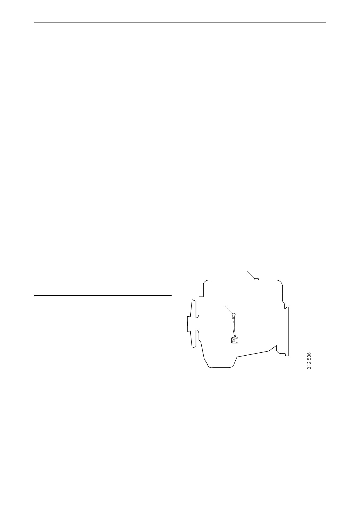
Checking the oil level
Note:
2
Leave the engine off for at least 7 minutes before
you check the oil level.
1
1. Remove the oil dipstick and check the oil
level. The correct level is between the mini-
mum and maximum marks on the oil dip-
stick.
2. Fill with more oil via the oil filler if the oil
level is at or below the minimum mark.
For information on the correct oil type, see the
section Oil grade.
23
Lubrication system
Changing the oil
WARNING!
Hot oil can cause burns and skin irritation. Wear
protective gloves and eye protection when
changing hot oil. Make sure that there is no pres-
sure in the lubrication system before changing
the oil. The oil filler cap must always be in place
when starting and running the engine to prevent
oil being ejected.
Note:
Change oil more often if the engine is subjected
to particularly demanding operation, such as a
dusty environment, or if deposits in the centrifu-
gal oil cleaner are thicker than 28 mm (1.1 in).
Renew the oil filter and clean the centrifugal oil
cleaner when changing oil.
Environment
Use a suitable container. Used oil must be dis-
posed of as specified in national and internation-
al laws and regulations.
1. Unscrew the oil plug and drain the oil when
the engine is hot. In certain engines the oil is
pumped out by means of a bilge pump. When
draining via the valve, the oil should be hot.
Alternatively, use a pump. This so that drain-
ing occurs more quickly.
2. Clean the magnet on the oil plug.
3. Refit the oil plug.
4. Fill with oil.
5. Check the level on the oil dipstick.
24

Lubrication system
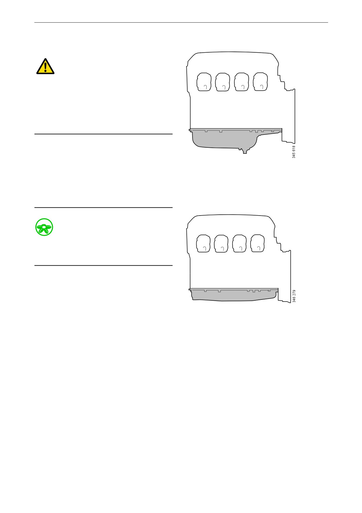
Maximum angles of inclina-
tion during operation
Maximum permissible angles of inclination dur-
ing operation vary, depending on the type of oil
25°
sump. See illustration.
25°
30°
30°
25°
25°
30°
30°
25

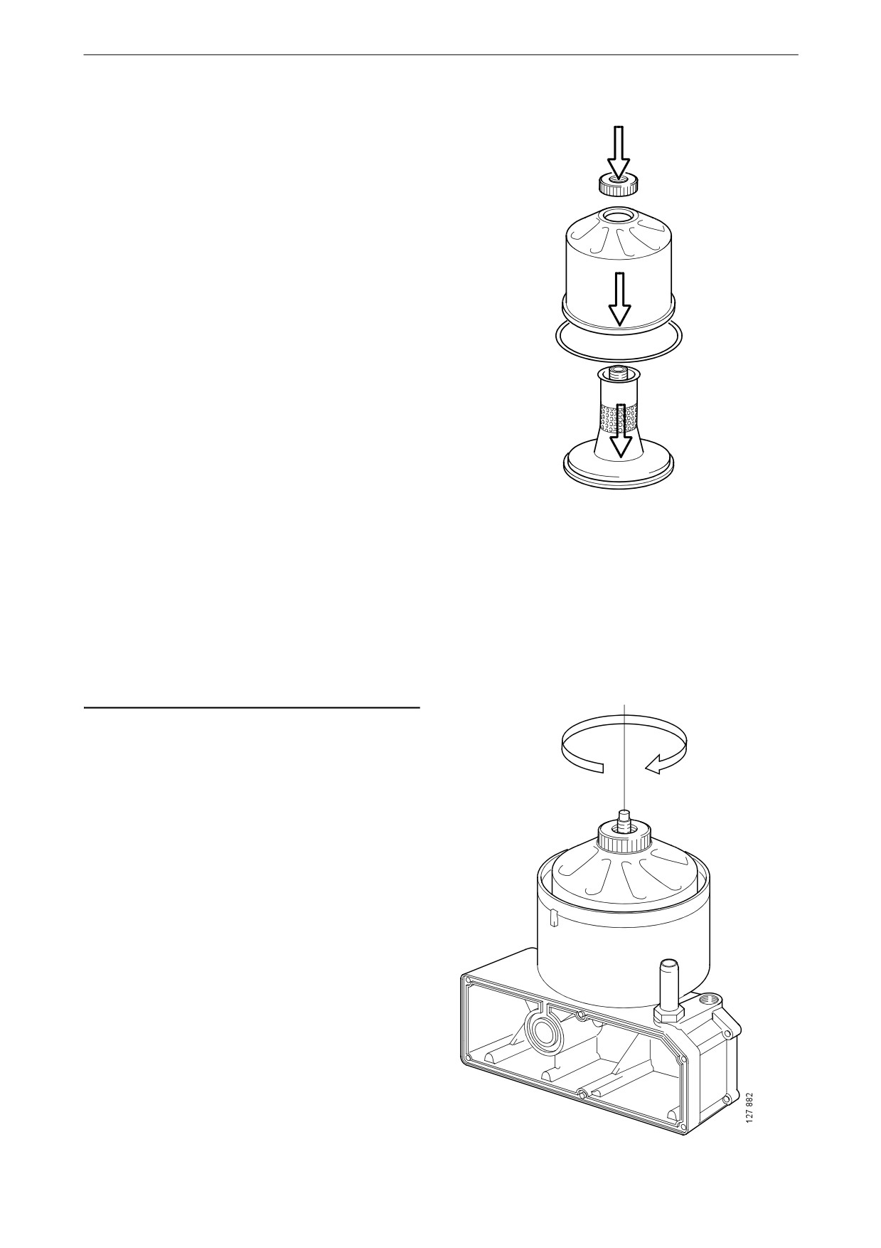
Lubrication system
Cleaning the centrifugal oil
cleaner
WARNING!
The oil may be hot. Carefully remove the cover
from the centrifugal oil cleaner.
Use eye protection and protective gloves when
working on the centrifugal oil cleaner.
When the centrifugal oil cleaner is cleaned, there
should be some dirt deposits on the paper in the
rotor cover. If the paper is clean, the equipment
is not working as it should. If this is the case, in-
vestigate the cause of this.
Renew the paper more frequently if the dirt de-
posits are thicker than 28 mm (1.1 inches) during
a scheduled oil change.
1. Clean the cover.
2. Unscrew the nut securing the outer cover.
3. Let the oil run out from the rotor.
x 1.5
4. Lift out the rotor. Wipe off the outside.
5. Loosen the rotor nut and unscrew it approx.
1.5 turns.
Note:
Take care not to damage the rotor shaft.
26

Lubrication system
6. If the rotor nut is jammed: Turn the rotor up-
side down and fasten the rotor nut in a vice.
See illustration.
7. Use protective jaws so as not to damage the
M20
grooves of the rotor nut.
8. Turn the rotor 1.5 turns anti-clockwise by
hand.
9. If this does not work: Screw two nuts togeth-
er with an M20 screw.
10. Position the screw head at the bottom of the
x 1.5
rotor.
11. Position a ring spanner on the lower nut and
turn the rotor 1.5 turns anti-clockwise.
IMPORTANT!
Do not attach the rotor directly to the vice. Never
strike the rotor cover.
12. Remove the rotor cover by holding the rotor
in both hands and tapping the rotor nut
against the table. Never strike the rotor di-
rectly as this may damage its bearings.
13. Remove the strainer from the rotor cover. If
the strainer is stuck, insert a screwdriver be-
tween the rotor cover and strainer and care-
fully prise them apart.
27

Lubrication system
14. Remove the paper insert.
15. Scrape off any remaining dirt deposits from
the inside of the rotor cover. If the deposits
on the paper are thicker than 28 mm (1.1 in),
the centrifugal oil cleaner must be cleaned
more often.
16. Wash the parts according to the applicable
industrial method.
17. Inspect the 2 nozzles on the rotor. Ensure that
they are not blocked or damaged.
Renew any damaged nozzles.
18. Check that the bearings are undamaged.
Renew damaged bearings.
1
19. Fold and fit a new paper insert on the inside
of the rotor cover as illustrated.
2
3
4
28
Lubrication system
20. Fit the strainer onto the rotor.
21. Fit a new O-ring to the foot of the centrifugal
oil cleaner.
22. Refit the rotor cover. Ensure that the O-ring
is not outside the edges, but is in the groove.
23. Screw the rotor nut back on by hand.
24. Check that the shaft is not damaged or loose.
Contact a workshop with qualified personnel
if the rotor shaft needs to be renewed.
Note:
Take care not to damage the rotor shaft.
25. Refit the rotor and rotate it by hand to make
sure it rotates easily.
29

Lubrication system
26. Fit a new O-ring in the cover.
27. Refit the cover and tighten the lock nut.
Tightening torque 20 Nm (15 lb-ft).
IMPORTANT!
To reduce the risk of oil leakage it is important to
tighten the cover to the correct tightening torque.
Operational testing of the
centrifugal oil cleaner
Operational testing need only be carried out if it
is suspected that the centrifugal oil cleaner is
malfunctioning. For example, if there are unusu-
ally few deposits given the distance driven.
1. Run the engine until it reaches normal oper-
ating temperature.
2. Stop the engine and listen for noise coming
from the rotor. It should continue rotating for
a time, even when the engine has stopped.
3. Use your hand to feel if the filter housing is
vibrating.
4. If the filter housing is not vibrating, disman-
tle and check the centrifugal oil cleaner.
30
Lubrication system
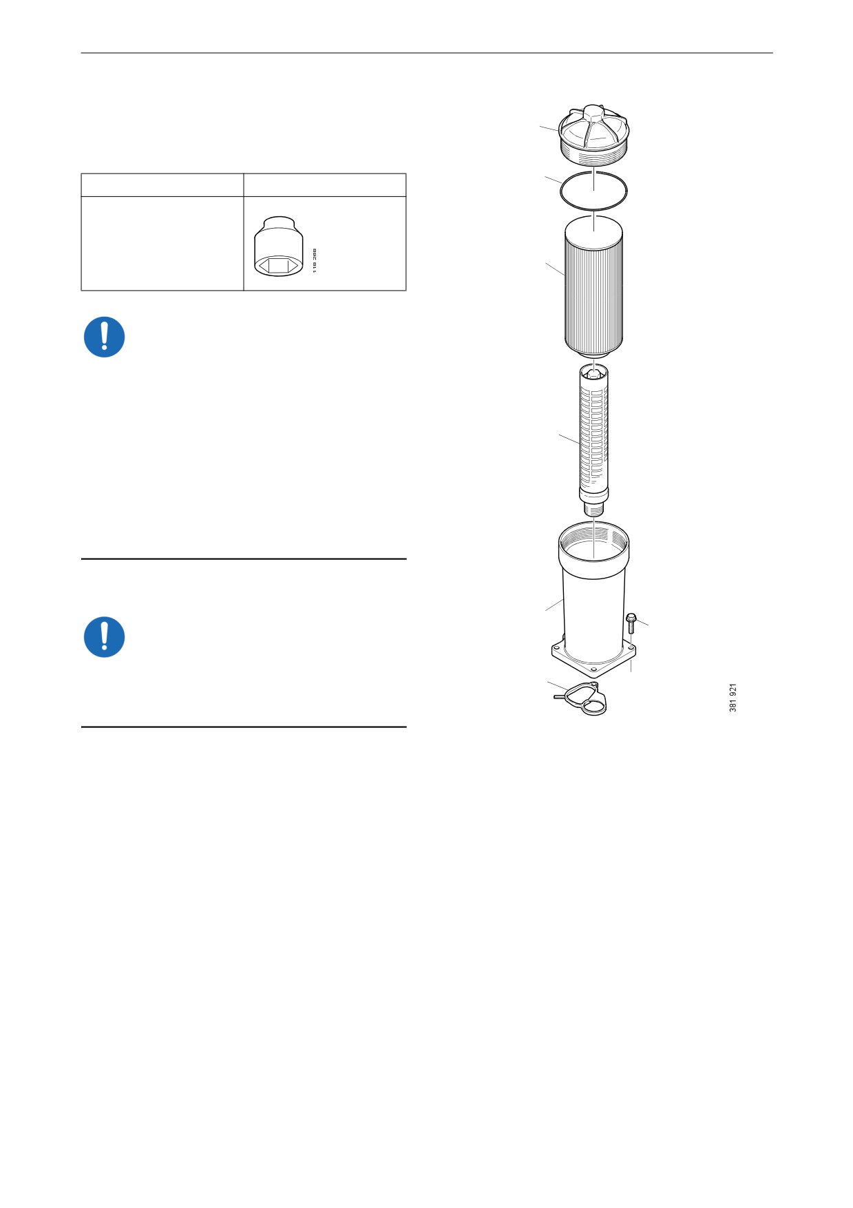
Renewing the oil filter
1
Tool
2
Designation
Illustration
Hexagon socket, 1/2",
36 mm
3
IMPORTANT!
Clean the centrifugal oil cleaner at the same time
as you change the oil filter. Otherwise, the oil fil-
ter will be blocked and resistance in the filter will
increase. If this happens, an overflow valve in
4
the filter retainer opens and lets the oil pass with-
out being filtered.
The engine must not be run without a filter ele-
ment in the oil filter. There is a risk of engine
damage caused by particles and by the oil pres-
sure being too low.
1. Unscrew the filter cover using the socket.
5
6
IMPORTANT!
Do not use an adjustable spanner or other open
7
tool, as there is a risk of damaging the filter cov-
er.
2. Lift out the filter housing cover with filter el-
ement. The filter housing will drain automat-
ically once the filter has been removed.
3. Undo the old filter from the cover by careful-
ly bending it to one side.
4. Fit a new O-ring on the cover. Lubricate the
O-ring with engine oil.
5. Press a new filter into the snap fastener in the
cover and tighten the filter cover to 25 Nm
(18 lbf/ft).
6. Make sure the oil filter drain has emptied the
oil from the filter housing. Screw on the filter
cover firmly with the socket.
7. Start the engine and inspect the filter housing
for leaks.
31