Scania DI14. Marine engine. Operator’s manual - part 3
AIR CLEANER
10. Daily:
READING THE
LOW PRESSURE INDICATOR
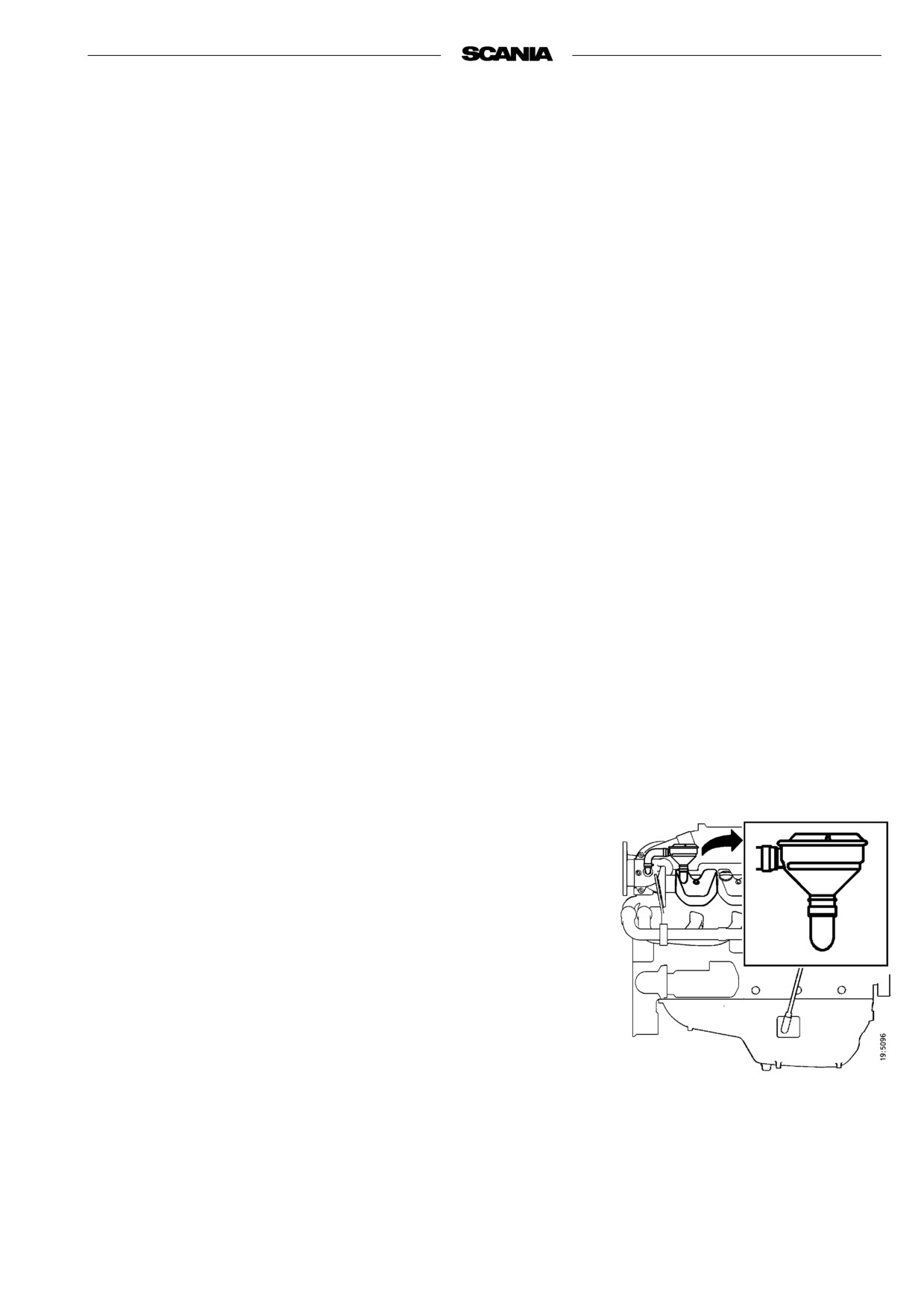
If the indicator’s red plunger is fully visible, change or clean the air cleaner
filter element, point 12.
The coarse cleaner must always
11. Every 200 hours:
be fitted in an upright position.
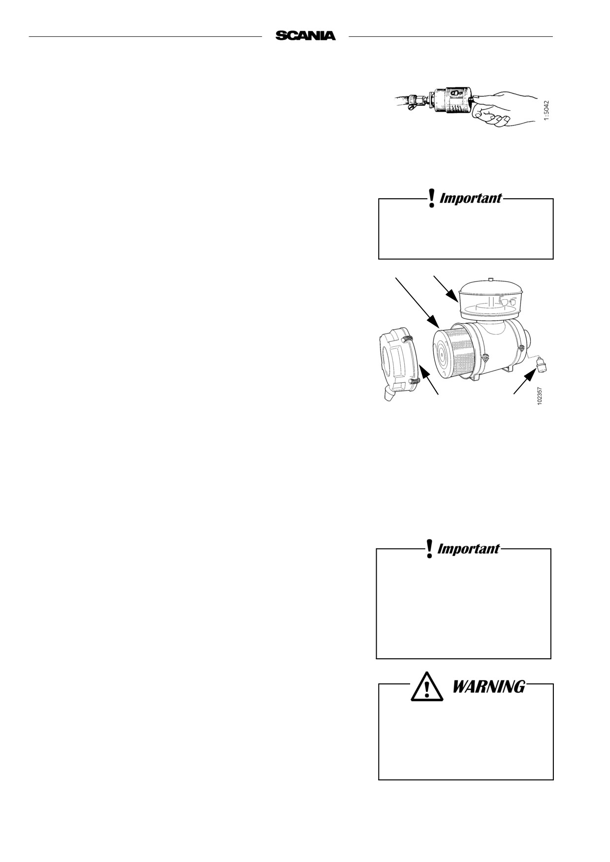
CLEANING THE AIR CLEANER
COARSE CLEANER
1
2
1. Remove the cover from the coarse cleaner.
2. Lift off the conical coarse separator. Remove the particles of dirt and
clean it.
3. Fit the coarse separator and screw down the cover.
3
4
1. Filter insert
12. Every 1200 hours:
2. Coarse cleaner
3. Cover
CLEANING OR CHANGING THE
4. Low pressure indicator
FILTER ELEMENT
Air cleaner with
Note Earlier if the vacuum indicator shows red
coarse cleaner
Disassembly
1. Remove the side cover from the air cleaner.
2. Change or clean the element.
Note Cleaning the element always entails a risk of damaging it. The
Only use Scania genuine air
element can only be cleaned a maximum of four times. After
filter. Change the filter element
cleaning, it has poorer dust capacity than a new element.
if it is damaged.
3. Mark the filter when it has been cleaned.
Danger of engine damage if the
Cleaning the element
filter element is damaged.
- Carefully blow the filter element clean using dry compressed air from
the inside.
Note This filter element must not be washed with water.
Never start the engine unless
the air filter is installed.
Danger of personal injury or
engine damage.
32

Checking
- Insert a flashlamp into the insert and check from the outside that there
are no holes or cracks in the filter paper.
- Change the filter insert if there is any damage at all. Danger of engine
damage.
Assembly
1. Assemble the air cleaner in reverse order.
2. Reset the red plunger in the vacuum indicator by pressing in the button.
Filter with a non-changeable element (unit cleaner)
Cleaning
- The filter may be cleaned a maximum of 3 times. Mark the filter after
each time it has been cleaned.
- Use a cleaning solution consisting of water mixed with approx. 1% mild
detergent.
1. Pour the cleaning solution into the element outlet at the same time as
turning the element so that the cleaning solution pours through the
element against the direction of the air flow.
2. Leave the element in the cleaning solution for 5 minutes and then take it
out so that all the cleaning solution drains away.
3. Rinse the element with ca 30 litres clean water at 30 - 40 °C. Pour the
rinsing water into the element in the same way as the cleaning solution.
4. Take out the element and allow the rinsing water to drain off.
5. Repeat the procedure until the rinsing water is clean.
6. Leave the element to dry in a warm place for a few days.
Note The element must not be dried with compressed air.
33

13. Every 2400 hours:
CHANGING SAFETY CARTRIDGE
Do not remove the safety
cartridge unnecessarily.
Note All filters are not fitted with safety cartridge.
1. Remove the side cover from the air cleaner.
2. Remove the filter insert.
3. Remove the safety cartridge.
4. Fit a new genuine safety cartridge.
5. Change or clean the filter element, see point 12.
1
6. Assemble the air cleaner.
1. Safety cartridge
Air cleaner with safety cartridge
Never clean the safety cartridge
34

FUEL SYSTEM
Be extremely careful with
14. Daily:
cleanliness when working on
the fuel system.
CHECKING FUEL LEVEL
Malfunctions
- Top up fuel if necessary.
can easily arise and the
- If the tank is run dry, bleed the fuel system, see point 15.
injection equipment
can be damaged.
15. Every 1200 hours:
CHANGING THE FUEL FILTER
Fuel tanks
- Drain any water from the fuel tanks.
Main filter
The filter consists of two parallel coupled filter units.
- Wash the outside of the filters and unscrew them. Dispose of the filters
according to environmental regulations.
- Do up the new filter by hand.
Never use tools for this. The filters can be damaged,
obstructing circulation.
- Bleed the fuel system as described below.
- Start the engine and check for leaks.
Bleeding the fuel system
- Open the bleed screw 1 on the main filter.
Only use Scania genuine fuel
- Pump the hand pump 2 until air-free fuel flows out at the maim bleed
filter.
screw.
- Close the bleed screw. Pump a few times using the hand pump.
If the engine is difficult to start after bleeding
- Slacken the injection pump overflow valve 3 one half turn
Always collect fuel in a suitable
and try starting again.
container to avoid spillage when
If the engine still won’t start
bleeding system or renewing
components.
- Pump the hand pump until bubble-free fuel flows from the overflow
valve.
- Tighten the overflow valve when the engine has started.
3
35

16. Every 2400 hours:
CHECKING THE INJECTORS
1. Socket nut
2. O-ring
Injectors should be inspected by trained personnel with access to the neces-
3. O-ring
sary equipment. Inspection should be carried out at least once a year or every
2400 hours.
4. Stop ring
5. Guide pin
Removal
6. Seal
1. Clean round the injectors and connections, including clamps and
brackets.
2. Detach the delivery pipe bundle and leak-off fuel lines.
3. Unscrew the injector.
4. Fit protective plugs on the injector and delivery pipe.
5. Lift up the seal from the bottom of the injector seat if it does not come
out together with the injector.
The delivery pipes must
6. Fit a core plug in the injector seat in the cylinder head.
not be bent.
7. Clean the injectors and check/adjust in a nozzle tester.
All clamps must be refitted.
Correct opening pressure, see Technical data, page 49.
Fitting
1. Check that there is no old seal in place and fit a new seal in the bottom
of the injector seat.
Always wear gloves and eye
2. Fit a new O-ring in the threaded socket nut and a new seal under the
socket nut.
protection when testing
injectors.
3. Fit the injector.
Fuel escaping under high
4. Tighten the socket nut to 70 Nm (7.0 kpm).
pressure can penetrate body
5. Fit the delivery pipe and tighten the cap nut to 20 Nm (2.0 kpm). Fit
tissue and cause serious injury.
clamps and brackets.
Important Take care to fit the delivery pipe without tension and make sure
that the cone on it is correctly positioned in the connection.
6. Fit the leak-off fuel line. Tighten the bolts to 11 Nm (1.1 kpm).
1. Delivery pipes
2. Cap nut
3. Washer
4. Cone
5. Connector on injector or
injection pump
Delivery pipe connection
36
ELECTRICAL SYSTEM
17. Every 200 hours:
Do not let open flame or sparks
CHECKING THE
come near the batteries.
ELECTROLYTE LEVEL IN BATTERIES
When batteries are charged,
they emit highly flammable
1. Undo the plugs and check the electrolyte level in all cells.
fumes that can explode.
2. Top up using distilled water until the level is 10-15 mm above the plates.
18. Every 200 hours:
CHECKING THE STATE OF CHARGE
IN BATTERIES
Note Every 200 hours applies to gensets and the like. Other installa-
tions every 1200 hours.
Wear gloves and eye protection
- Check the density with an acid tester.
when charging and
In a fully charged battery it should be:
handling batteries.
1,280 at +20 °C
Batteries contain a highly
corrosive acid.
1,294 at 0 °C
1,308 at -20 °C
- If the density is below 1.20, the battery must be charged.
A discharged battery freezes at -5 °C.
Do not rapid-charge the batteries. This will damage the battery in the
long run.
19. Every 200 hours:
Do not connect the cables to the
wrong terminals.
CLEANING BATTERIES
This could cause serious
damage to the electrical system.
Note Every 200 hours applies to gensets and the like. Other installa-
tions every 1,200 hours.
If the terminals are
shortcircuited, sparks
1. Clean batteries, cables and cable terminals.
will be generated.
2. Check that all cable terminals are firmly tightened.
3. Grease battery terminal posts and cable terminals with vaseline.
37

20. Every 1200 hours:
CHECKING THE COOLANT
LEVEL MONITOR
(optional equipment)
Note Check the coolant level monitor when the engine is cold.
1. Loosen clamping of level monitor cable on the engine and disconnect
the connector.
2. Put a container under the water-cooled exhaust manifold and unscrew
the monitor. Immediately insert a threaded plug M18x1.5 in the hole for
the monitor. Avoid contact with the skin when handling coolant.
3. Connect the monitor connector and put the control switch in the "ON"
position.
4. Check that the warning lamp remains on and that the buzzer sounds (if
fitted).
5. Lower the monitor into a metal container (steel) with liquid. It is impor-
tant that the monitor body is in contact with the metal.
6. After approximately 2 seconds the warning lamp should go out.
2-pole level monitor
7. Remove the monitor from the liquid. After approximately 7 seconds the
warning lamp will come on and the buzzer sound (if fitted).
8. Disconnect the monitor connector and screw on the monitor again.
9. Clamp the monitor cable as before and connect the connector.
10. Top up the system with coolant according to the specification on page
26.
38
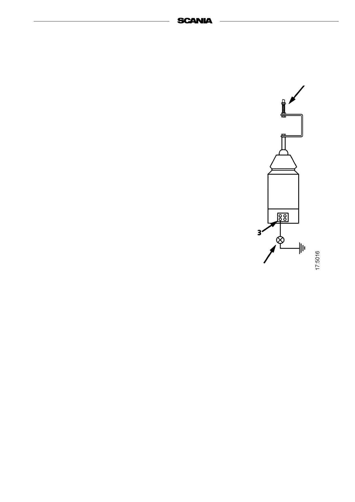
21. Every 1200 hours:
CHECKING THE TEMPERATURE
MONITOR
1. Drain the coolant, allowing the temperature monitor to be removed.
2. Remove the temperature monitor cable(s).
3. Unscrew the monitor.
C = Common connection
4. Refit the cable(s) to the monitor.
1 = Connection C -1 closes at
stamped temperature
5. Submerge the monitor sensor body in water. Heat the water slowly
(about 1° per minute) using e.g. an immersion heater.
2 = Connection C -2 opens at
stamped temperature
6. Set the control switch to "ON". Use a thermometer to check that the
warning lamp comes on or that an alarm is initiated at the correct tem-
2-pole temperature monitor
perature.
The correct temperature is stamped on the hexagonal part of the
monitor.
The temperature tolerance is ± 3°.
Always use a suitable container
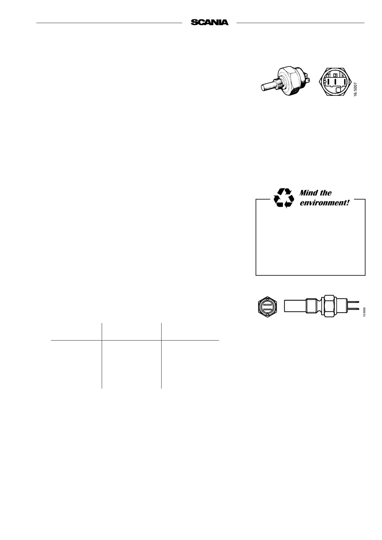
CHECKING TEMPERATURE SENSOR
to avoid spillage when
draining coolant.
1. Drain the coolant, allowing the temperature sensor to be removed.
Dispose of used coolant through
2. Remove the temperature sensor cable(s).
an authorized waste disposal
3. Unscrew the sensor.
contractor.
4. Connect an ohmmeter to the temperature sensor.
5. Submerge the sensor body in water. Heat the water slowly
(about 1° per minute) with for example an immersion heater.
6. Check the resistance at the temperatures given below.
7. The sensor should give the following readings:
2-pole temperature sensor
At temp. °C
Resistance Ω
Tolerance °C
60
134 ± 13.5
±4
90
51.2 ± 4.3
±3
100
38.5 ± 3
±3
39

22. Every 1200 hours:
Sensor function
Measure the sensor output voltage (pin 3) at different oil pressures. The
sensor output voltage shall be as follows:
0.85-1.15 bar
=
2.45 volt
1.80-2.20 bar
=
3.70 volt
2.75-3.25 bar
=
4.50 volt
3.79-4.20 bar
=
5.20 volt
4.55-5.45 bar
=
5.70 volt
5.40-6.6 bar
=
6.10 volt
The tolerances apply at +30°C - 110°C. At lower temperatures the tolerance
range is wider, e.g. 0°C = x 1.4.
Monitor function
Connect a test lamp to the oil pressure monitor, pin 4 (- ground), and check
that the monitor switches on at the correct pressure when the engine is started
and stopped. The monitor shall switch on at 0.7 ± 0.15 bar when the engine is
4
stopped.
1
Important The sensor/monitor must be supplied with voltage during the
measurement. Maximum 4 W load from a test lamp.
Monitor connected for automatic stop in case of a fault:
3
1. Start the engine.
2
2. Check on the oil pressure gauge that oil pressure rises.
3. Stop the engine manually (using the emergency stop).
4. Check on the oil pressure gauge at what pressure the stop solenoid oper-
ates and the monitor opens. Correct pressure: 0.7 ± 0.15 bar.
Monitor connected to buzzer:
1. Main power switch in operating position, check that buzzer sounds.
2. With the engine running, check that the buzzer falls silent when the oil
pressure is above 1.1 ±0.15 bar and the monitor closes.
23. Every 400 hours:
CHECKING THE STOP FEATURE
Check that the stop solenoid is activated and stops the engine when the stop
signal is given by the button, temperature monitor, coolant level monitor and
oil pressure monitor if these are coupled for automatic stop in the case of
fault.
40
CHECKING THE STOP SOLENOID
The following should be checked when changing the stop solenoid:
Plunger end position
Adjusting
- Connect a test lamp between connector pin 3 in the stop solenoid con-
screw
nector and battery negative.
- With the stop solenoid in energized position, the test lamp should light,
i.e. there should be power on pin 3). Adjust the stop solenoid linkage
until the test lamp lights (adjusting screw at yoke, see drawing) with the
solenoid energized.
The test lamp indicates that the pull coil is disconnected and that
the latch coil is connected.
If the pull coil is connected for more than 10 seconds, the solenoid is
damaged.
Test lamp
Check the stop arm on
the injection pump
RSV governor
- The stop arm should precisely touch the end stop in both operating and
stop positions.
RQ/RQV-K governor
- The stop arm should be against the mechanical stop inside the governor
housing in both operating and stop positions.
Important Adjust as necessary with the yoke adjusting nut.
41

CHANGING BATTERY
Removal
Do not connect the cables to the
1. Disconnect the negative cable (-) from the battery (cable connected to
wrong terminals.
ground).
This could cause serious
2. Disconnect the positive cable (+) from the battery (cable connected to
damage to the electrical system.
starter motor).
If the terminals are short-
Fitting
circuited, sparks will be
generated.
1. Connect the positive cable (+) to the battery (cable connected to starter
motor).
2. Connect the negative cable (-) to the battery (cable connected to
ground).
Dispose of used batteries
through an authorized waste
disposal contractor.
MISCELLANEOUS
24. Every 200 hours:
CHECK/TENSION V-BELTS
Correctly tensioned drive belts should be possible to depress
about 10 mm with a force of 35-50 N (depending on the free
length of the belt) when pressing on one belt.
Change worn or damaged belts.
1. Detach the securing screws.
2. Set the correct tension using the adjusting screw.
Do not over-tighten the belts.
Measurement using belt tension gauge Krikit
(Part. No. 587 495)
1. Zero the gauge by pressing the measuring arm.
2. Place the gauge on the V-belt at an equal distance from two pulleys.
3. Press until the gauge clicks.
4. Read the gauge.
- Recommended tension in Scania genuine belts
at test is 300 N.
- When changing belts, slightly higher (10-15%) tension should be used.
42

25. Daily:
CHECKING FOR LEAKAGE, RECTIFY
AS NECESSARY
- Start the engine.
- Check for oil, coolant, fuel, air and exhaust leakages.
- Tighten or change leaking connections. Check the overflow holes (1)
which show whether the O-rings between the cylinder liner and crank-
Ensure that any leakage does
case are leaking, see drawing.
not pollute the environment.
a) If coolant is leaking out, the two upper O-rings are leaking.
b) If oil is leaking out, the lower O-ring is leaking.
- Check that the drain hole (2) on the coolant pump is not blocked, see
drawing. If there is leakage, change the pump seal.
- Check that the drain for the “V” behind the injection pump is open all
In case of major leakage,
the way through the block and drain pipe so that no fluid can collect in
contact the nearest Scania
the “V”. See illustration.
workshop.
A small amount of leakage from the overflow holes during the engine’s
running-in period is normal. (Seals and O-rings are lubricated with soap
or oil when fitted.).
This leakage normally stops after a time.
43
26. Every 2400 hours:
CHECK/ ADJUST
VALVE CLEARANCE
Immobilise the starting device
when working on the engine.
Note Checking/adjusting valve clearances should also be carried out
after the first 400 hours of operation.
If the engine starts out of
control, there is a
Valves should be adjusted when the engine is cold, at least 30 minutes after
SERIOUS RISK
operation.
OF INJURY.
Rocker cover gaskets should be changed as necessary. Tightening torque:
25 Nm.
Intake valve clearance: 0.45 mm
Outlet valve clearance: 0.80 mm.
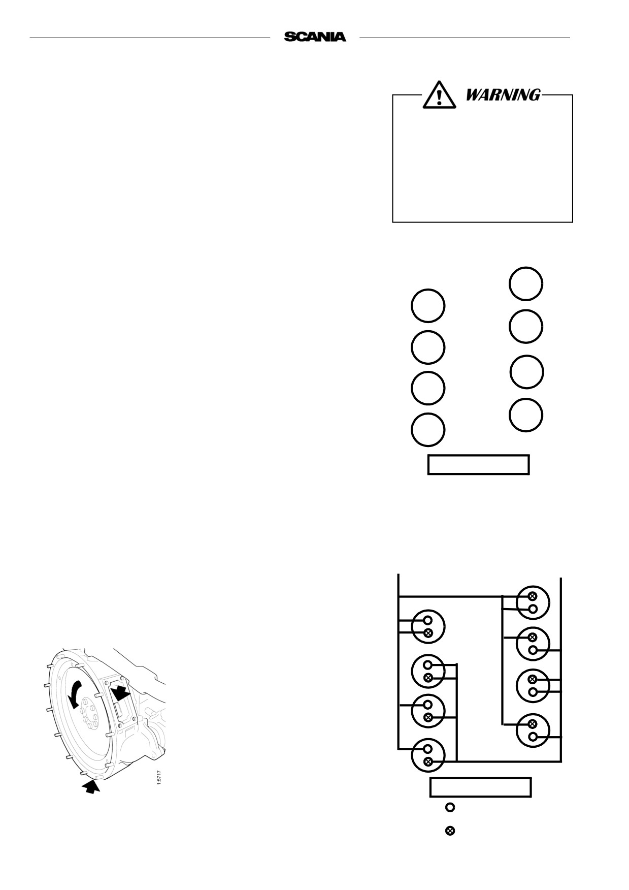
Alternative 1
- Turn the crankshaft in its direction of rotation until the No. 1 cylinder is
1
at 30 after TDC on the combustion stroke. There is a mark, ⊥ , at this
5
point.
2
- Adjust the following valves:
Right side Cyl 1
Intake and exhaust
6
2
Ex
4
Ex
3
Left side Cyl 5
In and ex
7
7
In
8
In
4
8
- Turn the crankshaft one revolution in its direction of rotation to the mark
⊥. The No. 1 cylinder piston is then at 30 after TDC in the induction
stroke.
FLYWHEEL
- Adjust the following valves:
Cylinder numbering
Right side Cyl 2
In
3
In and ex
No. 1 cylinder piston 30° after
4
In
TDC in
Left side Cyl 6
In and ex
combustion
induction
7
Ex
stroke
stroke
8
Ex
Note
On silumin casings readings can only be
taken from underneath.
On cast iron casings readings can be
taken from either underneath or from
the side (60o) according to the accessi-
bility.
FLYWHEEL
Intake valve
Covers for reading
on flywheel casing
Exhaust valve
44
Alternative 2
- Set the No. 1 cylinder to TDC by turning the engine in its direction of
rotation until both valves are closed.
- Adjust both the valves for the No.1 cylinder. Correct valve clearance is
indicated on the instruction plate on one of the rocker covers.
- Repeat this procedure with the remaining cylinders in the order
5 - 4 - 2 - 6 - 3 - 7 - 8 (firing sequence) by turning the engine 1/4 revolu-
tion in its direction of rotation between each adjustment.
27. Every 2400 hours:
CHANGING (or CLEANING) VALVE FOR
CLOSED CRANKCASE VENTILATION
Alternative 1:
Change the valve at the specified interval.
Alternative 2:
- Remove the valve after the specified interval.
- Clean the valve by placing it in a bath of diesel oil overnight. Then rinse
it several times in diesel and allow it to drip dry.
- Refit the valve.
- The valve may be reused (cleaned), maximum twice after the initial
2400 hours of operation. Take care to mark the valve after cleaning it.
45
LONG-TERM STORAGE
If the engine is not to be used for a lengthy period of time, special measures
should be taken to protect the cooling system, fuel system and combustion
chamber from corrosion and the exterior from rusting.
The engine can normally stand idle for up to six months. If it remains unused
for longer than this the following measures, which provide protection for
about four years, should be adopted.
Preparing the engine for long-term storage means:
- Thoroughly cleaning the engine
- Running the engine for a certain time using special preservative fuel, oil
and coolant.
- Otherwise preparing the engine for storage
(filter changes, lubrication etc.).
Preservative coolant
If the engine is to be stored with a full cooling system, use coolant containing
50% glycol by volume. Glycol without nitrite-based inhibitor must be used.
Ethylene glycol, if swallowed
E.g. BASF G48 or BASF D542.
can be fatal.
Avoid contact with the skin.
Preservative fuel
- Use diesel fuel oil mixed with Lubrizol 560A or the equivalent.
- Mix 1 cm3 (ml) Lubrizol 560A in 10 dm3 (l) of fuel.
!
HANDLING LUBRIZOL 560A
Hazardous!
Contains aromatic hydrocarbons
Use spot extractors where there is a danger of vapour build-up.
Wear protective gloves and goggles when handling Lubrizol. Do not use contaminated clothing.
In case of splashes in the eye: Rinse with moderate water spray (for min. 15 minutes). Seek medical attention.
In case of skin contact:
Wash affected areas with soap and water.
If you inhale it:
Fresh air, rest and warmth
Flammable:
Fire class 2A. Flash point + 27°.
In case of fire: Extinguish using carbonic acid, powder or foam
Storage:
In properly sealed container in a dry, cool place. Keep out of reach of children.
46
Preservative oil
Suitable preservative oil can be supplied by most petroleum companies.
For example: Dinitrol 40 or the equivalent.
Preparations for storage
-
Drain and flush the cooling system. Top up with preservative coolant.
-
Warm up the engine on regular fuel. Stop the engine and drain the oil.
-
Change the fuel filter and turbo filter.
Always use suitable containers
-
Fill the engine with preservative oil up to the minimum level on the
to avoid spillage when
dipstick.
draining oil and coolant.
-
Mix preservative fuel in a can. Detach the fuel pipe at the feed pump
Dispose of used oil and coolant
suction line and connect a hose from the can.
through an authorized waste
-
Detach the fuel pipe at the overflow valve and connect a return hose to
disposal contractor.
the can.
-
Start the engine and run it at about 1000 rpm (not single-speed engines)
for 20-25 minutes.
-
Stop the engine, remove the hoses and connect the regular fuel lines.
-
Oil the valve mechanism generously with preservative oil.
-
Remove the injectors and spray preservative oil into each cylinder,
max 30 cm3 (ml).
Turn the engine over a few times using the starter motor. Spray a small
amount of oil additionally into each cylinder.
After this the engine must not be cranked. Refit the injectors.
-
Drain the preservative oil from the engine. Fresh engine oil can be filled
directly or when the engine is taken out of storage.
-
Drain the coolant if the engine is not to be stored with a full cooling
system. Plug and tape over all coolant connections (if the cooling system
is not completely assembled).
-
Air cleaner: Clean or change the filter element.
-
Cover air intakes and exhaust pipes.
-
Alternator and starter motor:
-
Spray with water-repellent anti-corrosive oil, CRC 226, LPS1 or equal.
-
Spray the outside of bright metal engine parts, first with penetrating pre-
servative oil such as Dinitrol 25B and then with Dinitrol 112 or equal.
Winter storage
- In order to minmize the risk of condensation water in the fuel tank
during a winter stop it should be filled with fuel.
47