Scania DI14. Marine engine. Operator’s manual - part 2
Oil pressure
Max. oil pressure:
warm engine running at a speed above 800 rpm
6 bar
Normal oil pressure:
warm engine running at operating speed
3 - 6 bar
High lubricating oil pressure
Min. oil pressure:
(above 6 bar) is normal when
warm engine running at 800 rpm
0.7 bar
starting a cold engine.
At speeds below 800 rpm the gauge may show low oil pressure although no
fault is present.
Oil pressure below 0.7 bar at speeds above 800 rpm will cause engine
damage. The engine must be stopped immediately.
Charging indicator lamp
If the lamp comes on during operation:
- Check/adjust the alternator drive belts as described under the mainte-
nance point. See page 42.
- If the charging indicator lamp is still on, this could be due to an alterna-
tor fault or a fault in the electrical system.
STOPPING THE ENGINE
1. Run the engine without a load for a few minutes if it has been run con-
tinuously with a heavy load.
2. Stop the engine using the stop control. Engines with a stop solenoid and
fuel shut-off valve are stopped using the stop button. Hold the stop but-
There is danger of turbo damage
ton depressed until the engine has fully stopped.
and post boiling if the engine is
stopped without cooling.
3. Engines with battery master switch: Cut the power using the battery
master switch. (Does not apply to emergency power back-up units).
4. Set the control switch to 0. (Does not apply to emergency power back-
up units).
The power must not be switched
Emergency stop
off before the engine has
The stop solenoid linkage system has a knob marked ”STOP”. Pull the lin-
stopped.
kage system to the stop position using this knob if it is not possible to stop the
engine using the stop solenoid.
16
Clutch
- See the manufacturer’s instructions for handling and operating the
clutch.
WARNING If the clutch output shaft is rotating (e.g. in multiple
engine installations where other engines are running), the clutch
can, under its own power, be drawn to the engaged position.
THIS CAN CAUSE PERSONAL INJURY and engine damage.
For this reason, always secure the clutch in the disengaged posi-
tion if there is a risk of the output shaft starting to rotate.
CHECKS AFTER RUNNING
- Check that the power is cut from the battery master switch and that the
control switch is in the "0" position.
- Fill the fuel tank. Make sure that the filler cap and the area round the
Immobilise the starting device
filler opening are clean to avoid contamination of the fuel.
when working on the engine.
- If there is a risk of freezing, the cooling system must be drained if it
If the engine starts out of
does not contain a sufficient amount of glycol, refer to page 26.
control, there is a
SERIOUS RISK
- Close inlet valve for the sea water system (if fitted).
OF INJURY.
- If there is danger of freezing the sea water system must be emptied.
- At temperatures below 0 °C: Prepare for the next start by connecting the
engine heater (if fitted).
Top up engine coolant when the
engine has been stopped after
being started for the first time.
17
MAINTENANCE
The maintenance programme covers 27 points, divided into the following
main groups:
Lubrication oil system
page 20
Cooling system
page 24
Air cleaner
page 32
Fuel system
page 35
Electrical system, monitors, batteries etc. . .page 37
Immobilise the starting device
Miscellaneous
page 42
when working on the engine.
If the engine starts out of
The maintenance points are divided into intervals as follows:
control, there is a
Daily maintenance
SERIOUS RISK
OF INJURY
Maintenance before first start
Maintenance after the first 400 hours of operation
Periodic maintenance every 200 hours of operation (carried out after 200,
400, 600, 800 etc. hours)
Periodic maintenance after every 400 hours of operation (carried out after
400, 800, 1200, 1600 etc. hours)
Periodic maintenance after every 1,200 hours of operation (carried out after
1,200, 2,400, 3,600 etc. hours)
Periodic maintenance after every 2,400 hours of operation (carried out after
2,400, 4,800 etc. hours)
Periodic maintenance after every 4,800 hours of operation (carried out after
4,800, 9,600 etc. hours)
Annual every year
Maintenance every 5th year
ENGINES WITH FEW HOURS
OF OPERATION
Emergency back-up power units and the like which are not used regularly
should be test run and checked according to the unit manufacturer’s instruc-
tions.
The engine is run to operating temperature and the maintenance points below
should be carried out:
1. Checking oil level.
For engines with few operating
5. Checking coolant level.
hours that are not subject to
10. Checking low pressure indicator.
periodic maintenance according
to the maintenance schedule on
14. Checking fuel level.
page 19, maintenance should be
17. Checking electrolyte level in batteries.
carried out in accordance with
18. Checking battery charge.
the schedule:
19. Cleaning batteries.
"Every year"
25. Look for leaks. Remedy as necessary
"Every 5 years"
18
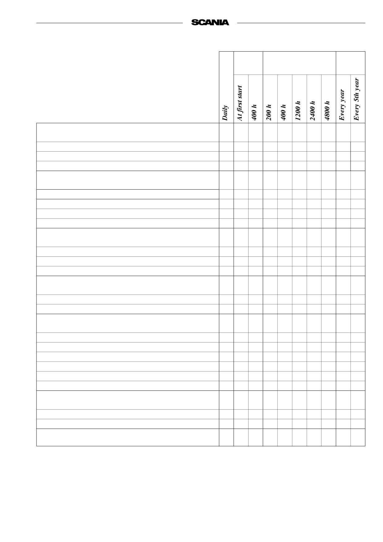
MAINTENANCE SCHEDULE
First
Interval
At least
time at
LUBRICATION OIL SYSTEM, page 20
1. Checking oil level
2. Oil change
1
3. Cleaning the lubrication oil cleaner
1
4. Changing the turbo filter
1
COOLING SYSTEM, page 24
5. Checking coolant level
6. Checking corrosion protection rods 4)
5
7. Checking seawater pump impeller 4)
5
8. Checking coolant
6
6
9. Cleaning cooling system
1
AIR CLEANER, page 32
10. Test reading low pressure indicator
11. Cleaning coarse cleaner
1
12. Cleaning or changing filter insert
3
13. Changing safety cartridge
FUEL SYSTEM, page 35
14. Checking fuel level
15. Changing main filter
1
16. Checking injectors
ELECTRICAL SYSTEM, page 37
2
17. Checking electrolyte level in batteries
18. Checking charge state of batteries
2
19. Cleaning batteries
2
20. Checking level monitor
21. Checking temperature monitor
22. Checking oil pressure monitor
23. Checking stop function
MISCELLANEOUS, page 42
24. Checking V-belts
25. Look for leaks. Remedy as necessary
26. Checking/adjusting valve clearance.
27. Changing (or cleaning) valve for closed crankcase
ventilation
1. More often if required
2. For engines with few operating hours, see page 18.
3. Earlier if low pressure indicator shows red.
4. Applies only to M engines with seawater pump.
5. Guidline values. Vary according to composition of seawater.
6. If inhibitor has not been topped up for five years, coolant should be changed.
19
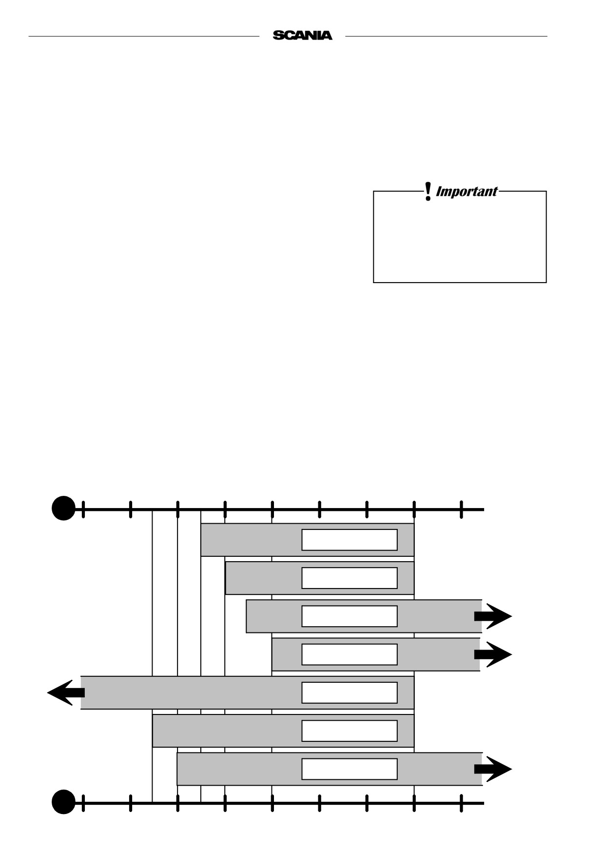
LUBRICATION OIL SYSTEM
OIL GRADE
The engine oil must at least meet the requirements for one of the following
oil classifications:
-ACEA E3, E4 or E5
- The Total Base Number (TBN) should be minimum 12-13
(ASTM 2896).
- Check with your oil supplier that the oil meets these requirements.
Additives must not be used.
- The specified oil change intervals apply provided that the fuel sulphur
content does not exceed 0.3% by weight. If the sulphur content exceeds
The oil should be suitable for all
0.3 % but is maximum 1.0%, the oil change intervals must be halved
temperature variations until the
(200 h).
next oil change.
- Viscosities as illustrated below.
- For operation at extremely low ambient temperature: Consult your
nearest Scania representative on how to avoid starting difficulties.
Oil analysis
Some oil companies can offer analysis of the engine oil. Such analysis
measures the oil TBN (Total Base Number), TAN (Total Acid Number), fuel
dilution, water content, viscosity and the quantity of friction particles and
soot in the oil.
The result of a series of analyses is used as the basis for establishing a
suitable oil change interval.
If the conditions are changed, a new oil analysis programme must be carried
out to establish the new change interval.
-40
-30
-20
-10
0
10
20
30
40
°C
SAE 20W-30
SAE 30
SAE 40
SAE 50
SAE 5W-30
SAE 10W-30
SAE 15W-40
20
1. Daily:
CHECKING OIL LEVEL
Note Before checking oil level: Allow the engine to remain stopped for
at least 1 minute.
- The correct level is between the marks on the dipstick. Top up when the
level is at the lower mark.
- Correct type, see ”Oil grade”, page 20.
Checking oil level during operation
On some engines, oil level can be checked during operation.
- Remove the oil filler cap to release the pressure in the crankcase.
- Check the level on the dipstick. Correct oil level: 10 mm below
Min. or Max. mark.
10 mm
10 mm
2. Every 400 hours:
OIL CHANGE
Note Under extremely severe operating conditions, especially in dusty
environment or if the deposits in the centrifugal cleaner are
thicker than 20 mm: change oil more frequently.
Max 30 dm3
Min 25 dm3
- Pump out the oil with the oil bilge pump when the engine is warm.
- Fill up with new oil.
- Check the level on the dipstick.
Max 26 dm3
Min 20dm3
WARNING
The oil may be hot.
Wear protective gloves and
goggles
Always use a suitable container
to avoid spillage when
changing oil.
Maximum angle of inclination during operation
Dispose of used oil through an
Maximum permissible angles during operation vary, depending on the type of
authorized waste disposal
oil sump, see illustration.
contractor.
Note Specified angle may only occur intermittently.
15°
18°
45°
35°
30°
30°
21
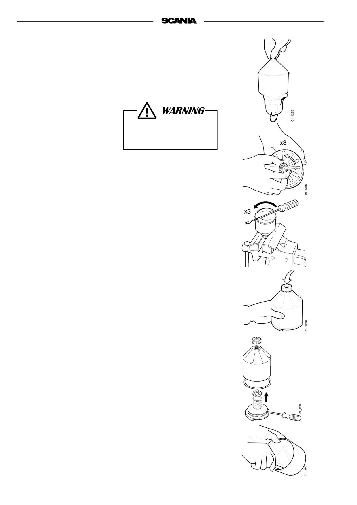
3. Every 400 hours:
CLEANING THE OIL CLEANER
(at same time as oil change)
- Unscrew the nut and remove the cover.
Open the cap carefully. The
oil may be hot.
- Lift out the rotor and slacken the rotor bowl retaining nut three turns.
- If the nut is jammed:
Clamp the nut, never the rotor, in a vice and turn the rotor three turns by
hand or with a screwdriver.
- Tap the nut lightly with your hand or a plastic hammer, to detach the
rotor bowl from the bottom plate.
- Unscrew the nut and remove the rotor bowl.
- Prise carefully to detach the strainer from the bottom plate.
- Scrape off the deposits from the inside of the rotor bowl. If there are no
deposits, this indicates that the cleaner is not working properly.
- If the deposits are thicker than 20 mm: clean more often.
22
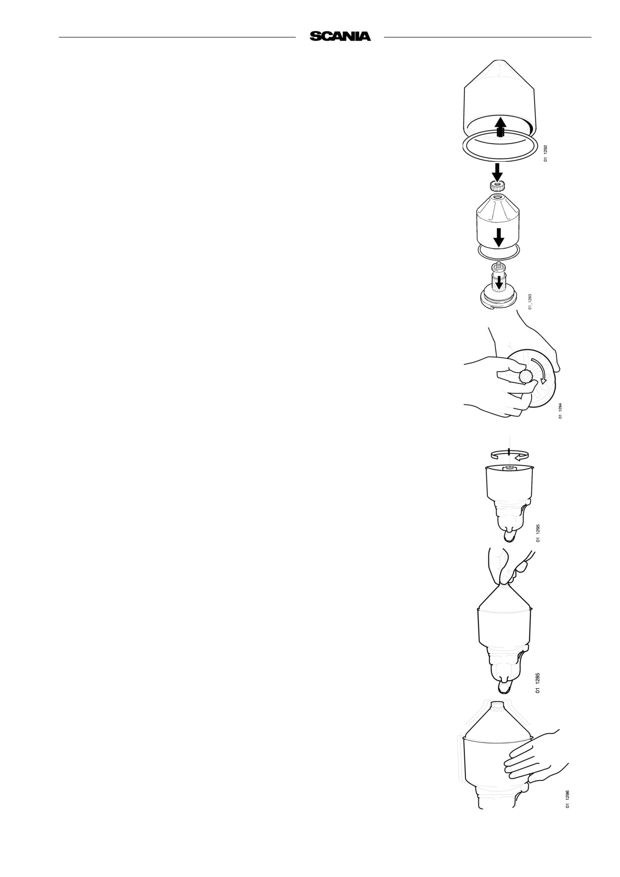
- Clean all parts in diesel fuel.
- Fit the O-ring in the rotor bowl. Make sure it is not damaged.
Change if necessary.
- Assemble the rotor
- Tighten the rotor nut firmly by hand.
- Refit the rotor.
- Make sure that it spins easily.
- Check that the O-ring in the bowl is undamaged.
A hardened or damaged O-ring must be changed.
- Screw the bowl down hard by hand
If the nut is tightened using a tool, the rotor shaft, nut or bowl may be
damaged.
Operational test
The rotor spins very fast and should continue to rotate when the engine has
stopped.
- Stop the engine when it is warm.
- Listen for the whirring from the rotor or feel whether the cleaner hous-
ing is vibrating.
The rotor normally rotates 30 - 60 seconds after the engine has stopped.
If not: Dismantle and inspect.
23
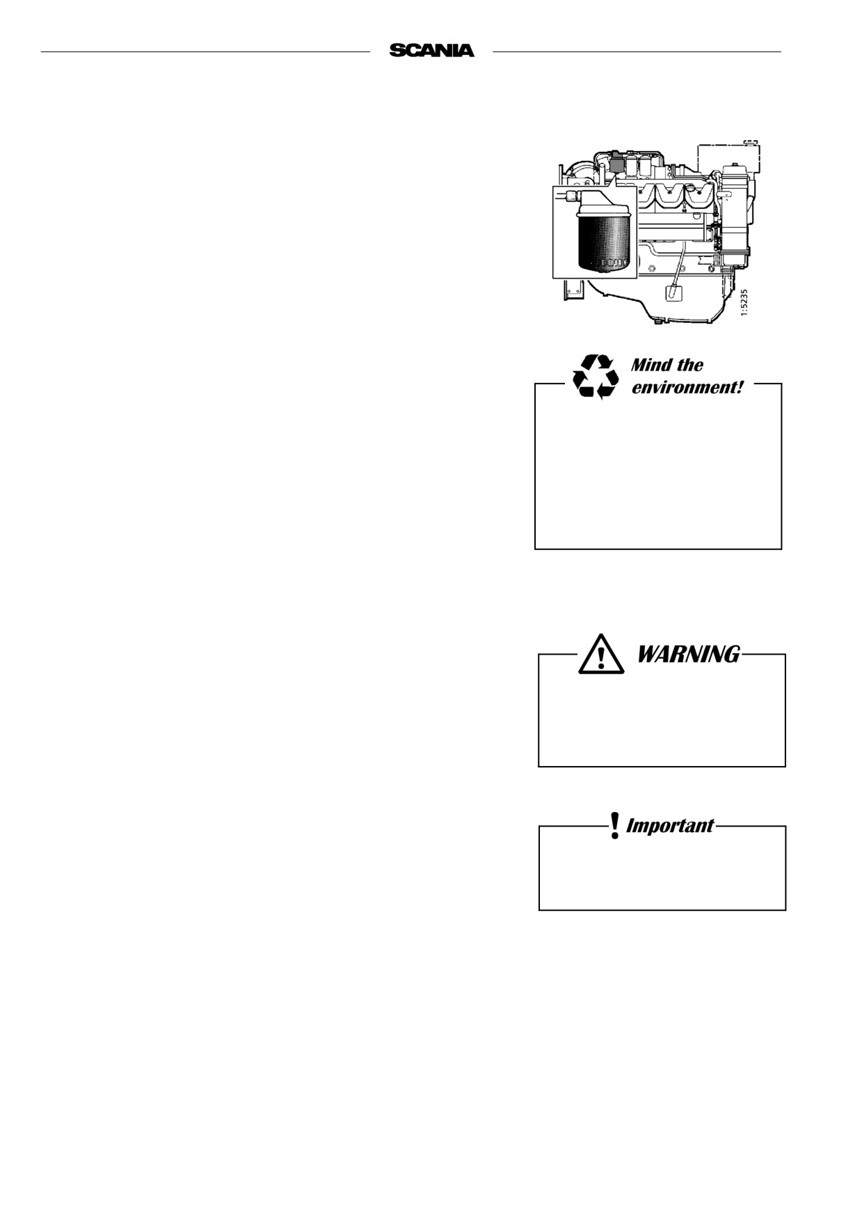
4. Every 400 hours:
CHANGING THE TURBO FILTER
(at the same time as the oil change)
- Remove the old filter.
- Oil the rubber gasket and fit a new genuine Scania filter.
- Tighten the filter by hand.
Never use a tool for tightening. The filter could be damaged, obstruc-
ting circulation.
- Start the engine and check for leaks.
Important If the deposits in the centrifugal cleaner exceed 20 mm the oil
filter must be changed at more frequent intervals, at the same
time as the centrifugal filter is cleaned and the oil changed.
Always collect oil in a suitable
container to avoid spillage when
renewing the oil filter.
Dispose of used filters through
an authorized waste disposal
contractor.
COOLING SYSTEM
5. Daily:
CHECKING COOLANT LEVEL
- Open the expansion tank filler cap and check the coolant level.
Carefully open the cap.
Hot water and steam
- Correct level: (Scania expansion tank) .
may blow out.
- Cold engine: Coolant level should reach the lowest part of the
filler pipe.
- Warm engine: Coolant level should be between 10-20 mm above the
lowest part of the filler pipe.
- Other types of expansion tank according to the installer’s instructions.
- Top up the coolant as necessary, see point 6.
Always top up with ready mixed
coolant.
Note When filling large amounts of coolant:
Never pour cold coolant into a hot engine.
This could cause cracks in the cylinder block and the cylinder
head.
24
6. Every 400 hours:
CHECKING CORROSION BARS
(Only engines with heat exchanger)
- Empty the sea water circuit and check the corrosion bars (protection
anodes). Located as illustrated.
- Scrape off all loose material on the anode.
- Change if less than half the bar is left.
A new bar is 55 mm long with a diameter of 17 mm.
Important If the corrosion bars are very corroded they need to be checked
more often, for example every 200 hours.
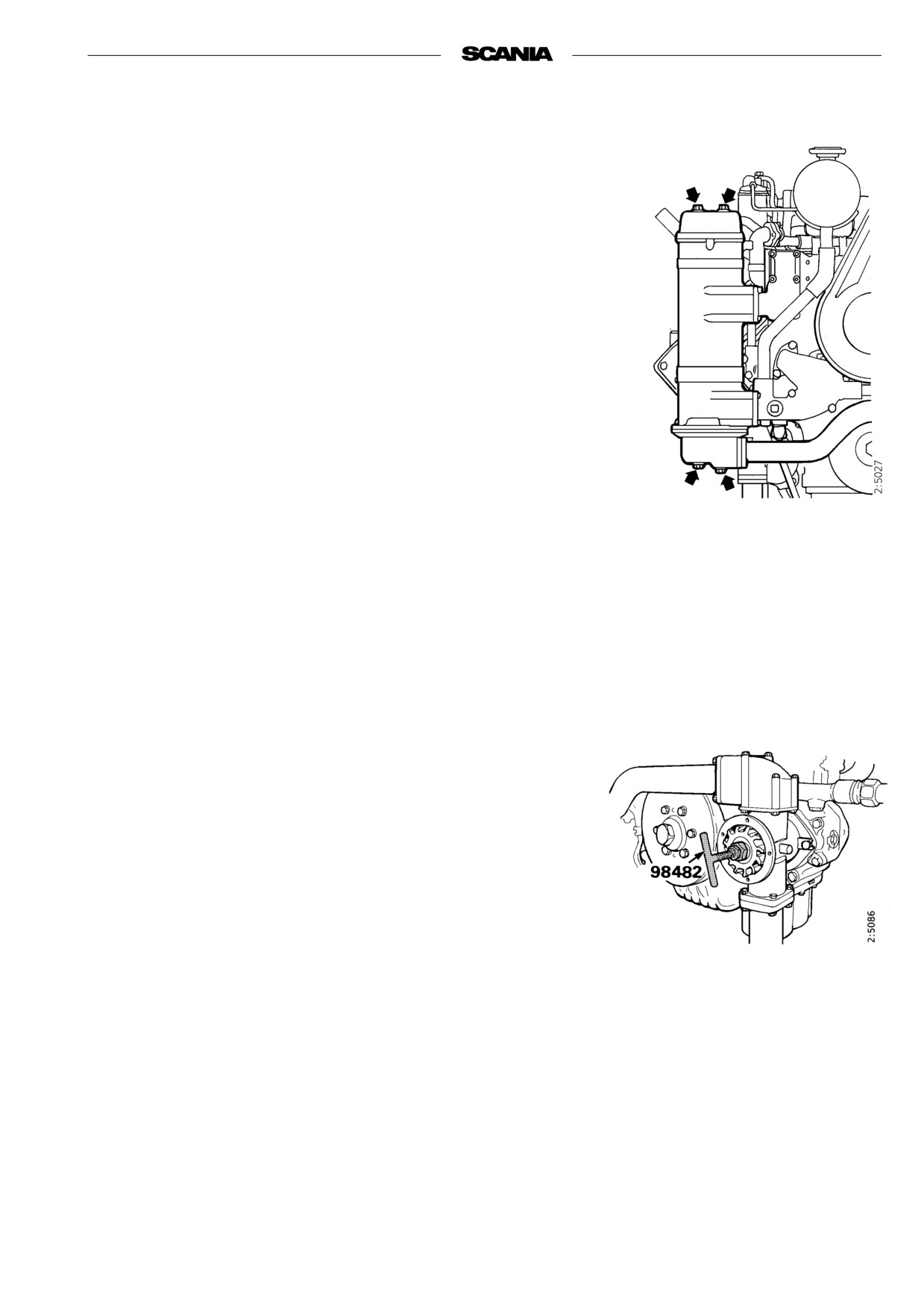
7. Every 400 hours:
CHECKING THE SEAWATER PUMP
IMPELLER
(Only engines with heat exchanger)
- Close the bottom valve if the seawater pump is below the water line.
- Empty the sea water circuit.
- Take off the seawater pump cap.
- Check that the impeller vanes are not worn or damaged.
Important If the impeller must be changed frequently, the cleaning of th
sea water must be improved.
Changing the impeller
- Pull out the impeller with puller 98 482 (Scania Special Tools).
- Fit new impeller and cap. Check that the cap seal is not hard or dam-
aged.
Note A spare impeller should be kept on board.
- The impeller can be deformed at longer periods of inactivity. Change
before or remove the impeller before longer periods of stoppage. Also
see "Preparations of storage".
25
8. Every 2400 hours:
CHECKING THE COOLANT
Coolant should be checked as follows:
Coolant composition:
a) Check the appearance of the coolant.
If there is a danger of freezing:
b) Coolant with glycol: Check the glycol content.
minimum 30% glycol by
c) Coolant with Scania Anti-corrosive:
volume
Check the protection against corrosion.
maximum 60% glycol by
volume
The composition of the coolant is also described under
If there is no danger of freezing:
“Starting and running”
7-12% by volume
Scania Anti-corrosive
a)
Checking the appearance of the coolant
- Fill a receptacle with a little coolant and check that it is clean and clear.
- If the coolant is contaminated or cloudy, consider changing it.
- Water added to the coolant should be clean and free from dirt of any
kind.
- Use drinking water with a pH of 6 - 9.
b)
Checking glycol content
If there is a danger of freezing, use only glycol as an anti-corrosive in the
coolant.
Ethylene glycol is highly
- Cooling systems with glycol should contain at least 30% glycol by
dangerous if ingested and can
volume to provide acceptable protection against corrosion.
prove fatal.
- A content of 30% glycol by volume protects against freezing down to
Avoid skin contact with glycol.
-16°C. If further protection is needed, refer to the table on the next page
for calculating the required amount of glycol.
We recommend only nitrite-free anti-freeze glycol with the following sup-
plier designations:
BASF G48 or BASF D542
The coolant should be ready
- Always top up the anti-freeze if its glycol content drops below 30% by
mixed when it is poured into the
volume. A glycol content above 60% by volume will not provide greater
cooling system.
protection against freezing.
Never top up with only water or
- The table shows the temperature at which ice starts to form. The engine
only glycol.
will freeze and fracture at appreciably lower temperatures, see diagram.
- Ice forming in the coolant often causes malfunctioning without any risk
of damage. The engine should not be subjected to heavy loads when ice
starts to form.
Note Change the coolant when cleaning the cooling system: Every 4800
The recommended glycol must
hours or minimum every 5 years.
not be mixed with glycol having
nitrite-based anti-corrosive.
Important If a coolant filter is used in the cooling system, it must not con-
tain an inhibitor.
Risk for build up of sludge and
reduced cooling capacity.
26
% Glycol by volume
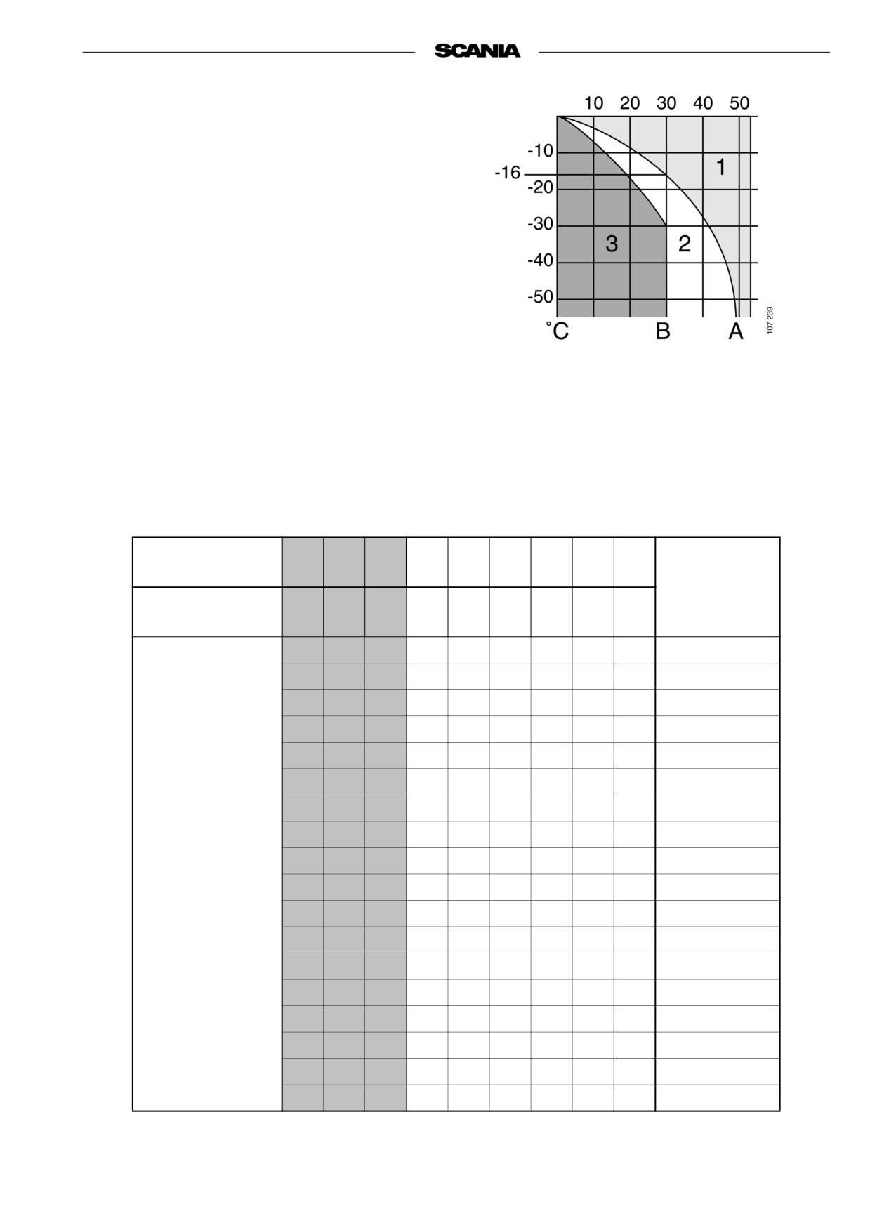
Characteristics of glycol at low temperatures:
- Example with 30% glycol by volume
- Ice slush starts to form at -18 °C
- There is risk for malfunctions at -30 °C
- The engine cannot freeze and fracture with a
minimum of 30% glycol by volume
Curve A: Ice build up starts (slush)
Curve B: Temperature at which damage due to
freezing can occur
1. Safe range
2. Malfunctions may occur (ice slush)
3. Risk of damage by freezing
A
% glycol by
15
20
25
30
35
40
45
50
60
Cooling
volume
system
Ice slush starts
capacity, dm3
-6
-9
-12
-16
-22
-27
-36
-46
-55
to form at °C
5
6
8
9
11
12
14
15
18
30
6
8
10
12
14
16
18
20
24
40
8
10
13
15
18
20
23
25
30
50
9
12
15
18
21
24
27
30
36
60
11
14
18
21
25
28
32
35
42
70
12
16
20
24
28
32
36
40
48
80
14
18
23
27
32
36
41
45
54
90
15
20
25
30
35
40
45
50
60
100
Glycol dm3
17
22
28
33
39
44
50
55
66
110
(litres)
18
24
30
36
42
48
54
60
72
120
20
26
33
39
46
52
59
65
78
130
21
28
35
42
49
56
63
70
84
140
23
30
38
45
53
60
68
75
90
150
24
32
40
48
56
64
72
80
96
160
26
34
43
51
60
68
77
85
102
170
27
36
45
54
63
72
81
90
108
180
29
38
48
57
67
76
86
95
114
190
30
40
50
60
70
80
90
100
120
200
A= Area to be avoided. Only for calculating glycol mix.
Coolant freezing temperature when ice starts to form at different glycol mixes
27
c)
Checking Protection against corrosion
There must always be sufficient anti-corrosive (inhibitor) in the coolant to
Corrosion inhibitor, if
protect the cooling system against corrosion.
swallowed can be fatal.
If there is no danger of freezing use only Scania Anti-corrosive.
Avoid contact with the skin.
The inhibitor in Scania Anti-corrosive is nitrite-free.
The correct proportion of anti-corrosive is 7-12% by volume.
- Topping up with 1.0% Scania Anti-corrosive by volume should be done
after every 2400 hours of operation.
Mixing corrosion inhibitor with
- Never top up with only water or only anti-corrosive!
glycol or adding too much
Fluid losses must always be replaced with premixed coolant:
corrosion inhibitor may cause
water + 10% by volume of Scania Anti-corrosive.
deposits and reduced cooling
Note The coolant should be changed when the cooling system is clea-
capacity.
ned: every 4,800 hours or minimum every 5th year.
If a coolant filter has been fitted
it must not contain inhibitor.
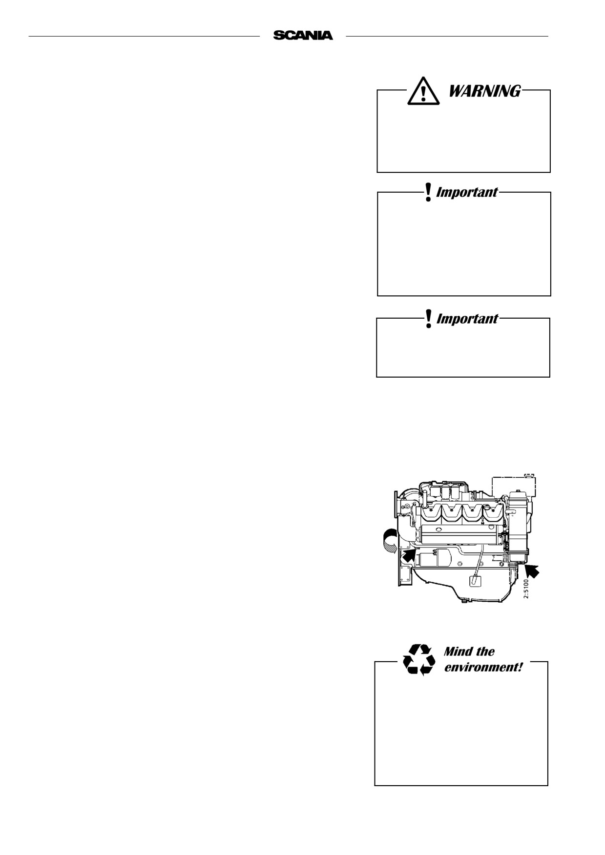
Changing coolant
1. Remove the filler cap from the expansion tank.
2. The coolant is drained at two points as illustrated:
- the ”lowest point” of the engine block, see drawing
- the ”lowest point” of the cooling system.
3. Close the valves.
4. Top up with coolant through the expansion tank filler hole.
Mix coolant as described on page 26.
Always collect fluid in a suitable
container to avoid spillage when
changing coolant.
Dispose of used coolant through
an authorized waste disposal
contractor.
28
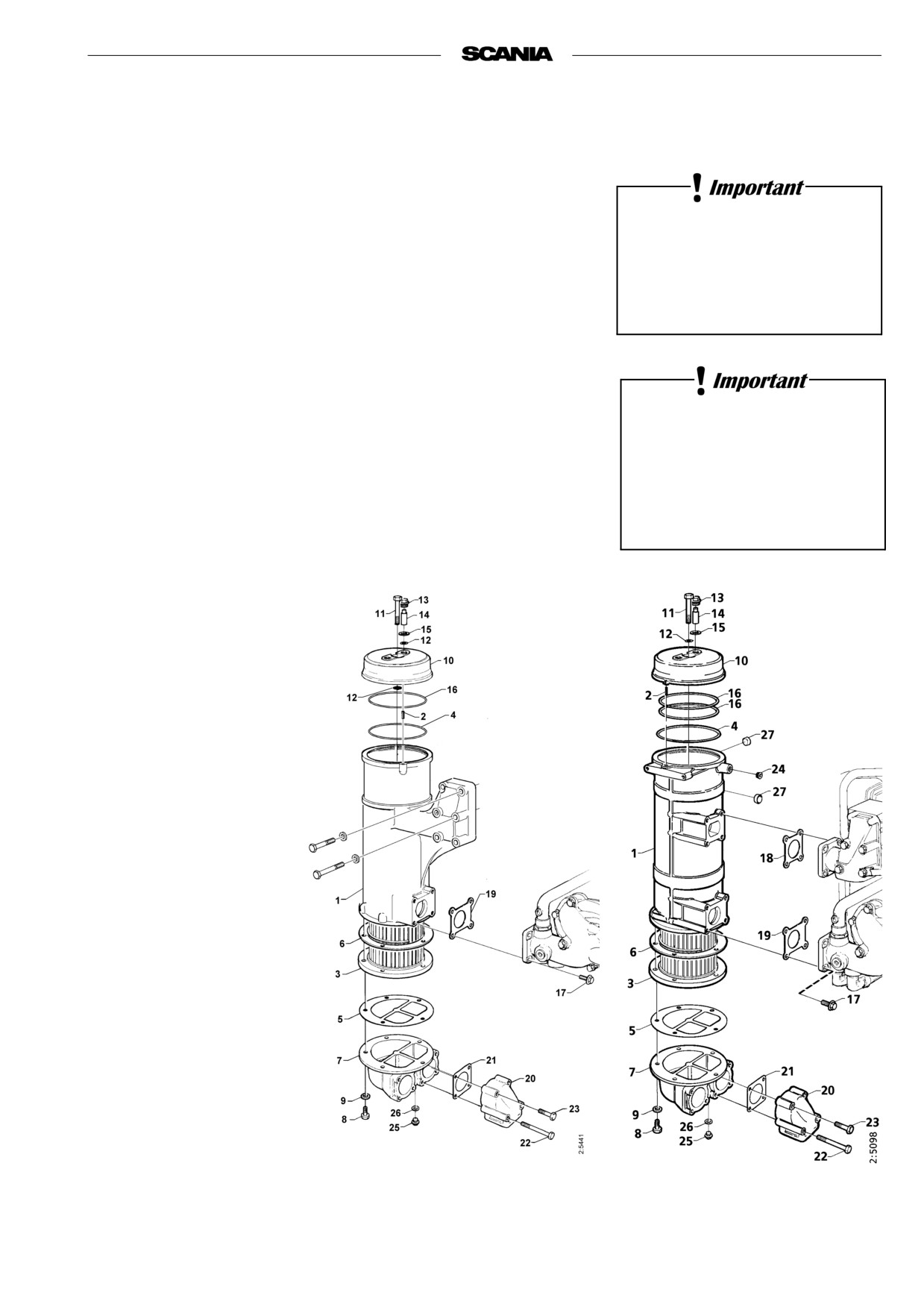
9. Every 4800 hours:
CLEANING THE COOLING SYSTEM
Note If necessary, the cooling system should be cleaned more often.
External cleaning
The cooling system must never
Heat exchanger
be cleaned with caustic soda.
1.
Drain the coolant from the engine, see “Changing coolant”.
There is a risk of damage to
aluminium parts.
2.
Drain the seawater circuit.
3.
Detach the heat exchanger hose and pipe connections.
4.
Dismantle the heat exchanger as illustrated.
5.
Clean the outside of the element. Use a paraffin-based engine cleaner.
6.
Any deposit on the inside of the pipes is removed mechanically using a
There are springs and seal
round rod.
strips in the heat exchanger to
7.
Assemble the heat exchanger with new gaskets and O-rings.
the right, between the housing
Grease O-ring 4 before fitting.
and the element, which are not
8.
Refit hose and pipe connections.
illustrated.
9.
Fill the system with coolant as described on page 26.
1.
Housing
2.
Spiral pin
3.
Element
4.
O-ring
(DSI only)
5.
Gasket
6.
Gasket
7.
Cover
8.
Screw
9.
Screw
10.
Cover
11.
Screw
12.
O-ring
13.
Plug
14.
Protective anode
15.
Gasket
16.
O-ring
17.
Screw
18.
Gasket
19.
Gasket
20.
Flange pipe
21.
Gasket
22.
Screw
23.
Screw
24.
Plug
25.
Plug
26.
Washer
DI14 68, DI14 75
27.
Plug
29
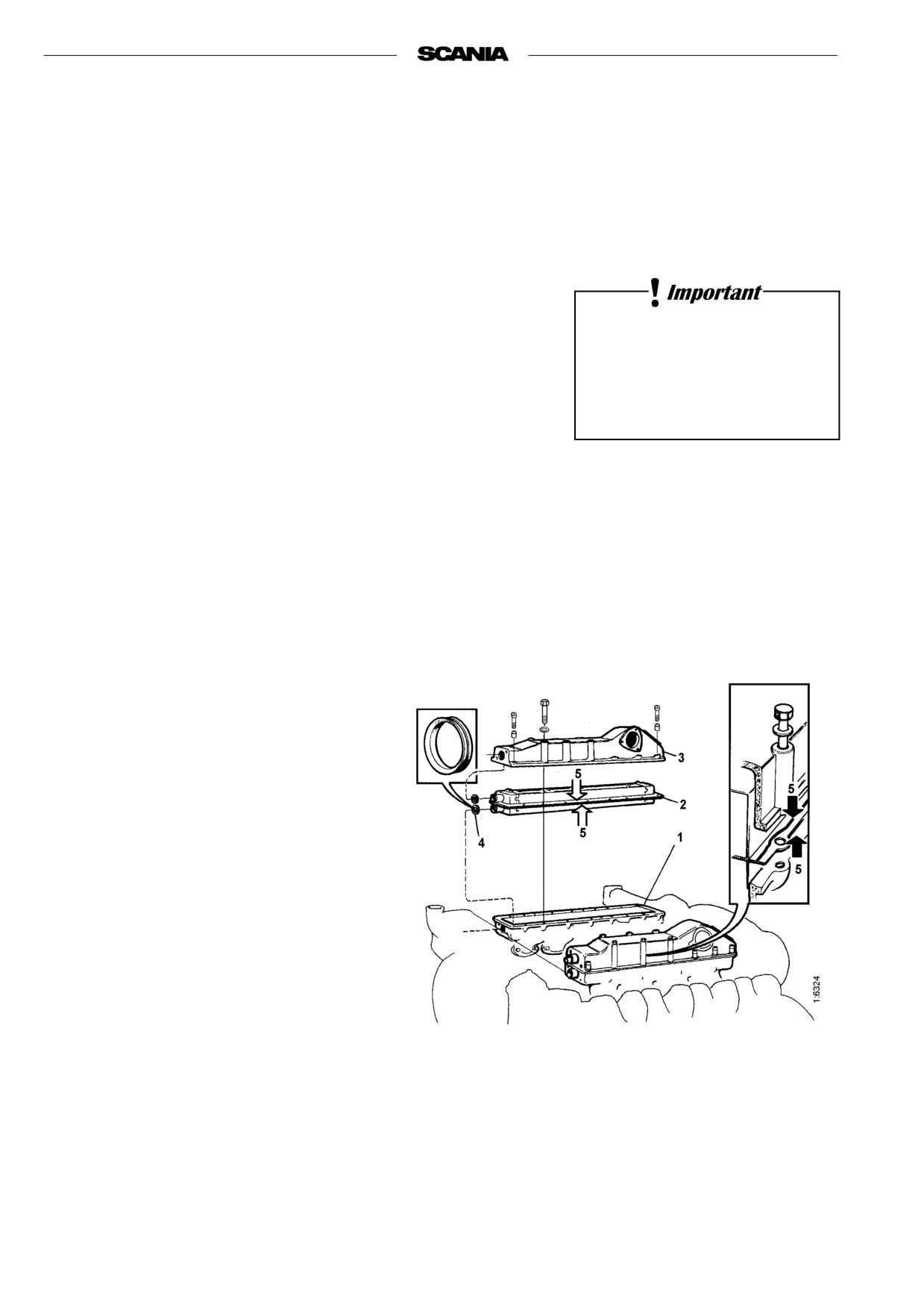
Charge air cooler
1. Drain the coolant from the engine, refer to “Changing coolant”.
2. Detach the charge air cooler inlet and outlet connections.
3. Detach the upper part of the intake manifold.
4. Dismantle the charge air cooler as illustrated.
Be careful - do not damage the core water connections.
5. Clean the outside of the element. This is especially important if the
engine is equipped with closed crankcase ventilation. Use a paraffin-
based engine cleaner.
6. Clean and degrease the sealing surfaces on the core and the air intake
The cooling system must never
manifold upper and lower parts with a spirit based cleaner.
be cleaned with caustic soda.
7. Apply sealant (silicone 816 064) in a uniform bead, approximately
There is a risk of damage to
2-3 mm, on both sealing surfaces of the element.
aluminium parts.
8. Fit new V-ring seals on the connections of the element.
9. Assemble the charge air cooler within 15 minutes of applying the sea-
lant. Torque tighten the bolts to 50 Nm.
10. Refit the inlet and outlet connections with new O rings.
11. Connect the intake manifold from the turbo.
12. Fill up with coolant according to the specification
on page 26.
Important Allow the sealant to cure for minimum
24 hours before the engine is used.
1. Intake manifold,
lower part
2. Radiator element
3. Intake manifold,
upper part
4. V-ring seal
5. Sealant 816 064
Engines without heat exchanger (keel-cooling)
1. Check cooling elements/cooling pipes on the inside and outside of the
keel.
2. Clean as necessary using a paraffin-based engine cleaner or carefully
scrape off deposits from external pipes.
Take care - do not damage cooling elements or cooling pipes.
30
Internal cleaning
Removing oils and greases
- If possible, run the engine until it has reached the operating
temperature and then drain the cooling system.
- Remove the thermostats.
- Fill the system with clean, hot water mixed with liquid dishwasher
detergent designed for household use.
Concentration 1% (0.1/10 l).
Handling cleaning agents for
the cooling system:
- Run the engine until warm for about 20-30 minutes. Do not forget the
cab heating system (if fitted).
Read the warning label on the
- Drain the cooling system.
container.
- Fill the system again using clean, hot water and run the engine for
approximately 20-30 minutes.
- Drain the water from the system.
- Refit the thermostats.
- Fill up with new coolant according to the specification on page 26.
Removing deposits
- If possible, run the engine until it has reached the operating temperature
and then drain the cooling system.
- Remove the thermostats.
Always collect fluid in a suitable
container to avoid spillage when
- Fill the system with clean, hot water mixed with one of the
commercially available radiator cleaners based on sulphamic acid and
draining coolant.
containing dispersing agents. Follow the manufacturer’s instructions for
Dispose of used coolant through
mixing proportions and cleaning times.
an authorized waste disposal
- Run the engine for the specified time and then drain the cooling system.
contractor.
- Refill the system with hot water and run the engine for approximately
20-30 minutes.
- Drain the water from the system.
- Refit the thermostats.
- Fill up with new coolant according to the specification on page 26.
Preventive replacement of coolant pump gear wheel
Note Should be carried out when cleaning the cooling system.
- Detach the coolant pump.
- Remove the gear wheel.
- Fit a new gear wheel and tighten the nut with 200 Nm.
Note The tightening torque must no be applied across the gear wheel..
- Refit the coolant pump with new gaskets against the timing gear hous-
ing.
31