Scania DI14. Marine engine. Operator’s manual - part 1
Industrial & Marine Engines
IMPORTANT INFORMATION
When working on the engine, e.g. when adjusting the belts, changing oil or adjusting the clutch it is
important that the engine does not start. The engine may be damaged but above all there is -
!
SERIOUS RISK OF INJURY.
For this reason, always secure the starting device or disconnect a battery cable
before working on the engine.
This is especially important if the engine has a remote starter or automatic starting.
This warning symbol and text is reproduced beside those maintenance points where it is
especially important to consider the risk of injury.
Operator’s Manual
DI14
Marine engine
opm96-14m en
1 588 297
START-UP REPORT - WARRANTY
When the start-up report has been filled in and sent to Scania there is a 1 year warranty starting from
the start-up date. Also enter the below information since this will facilitate contacts with e.g. service
workshops.
Engine number
Start-up date
User’s name and address
Signature
Engine type
Variant
Engine type and variant are indicated on the engine type plate
FOREWORD
This operator’s manual describes the operation and maintenance of the Scania
DI14 marine engines. The instructions apply to engines in program 96, start-
ing with engine number 5 562 819.
The engines are direct injection, fluid-cooled, four-stroke diesel engines with
8 cylinders in a V-configuration. The engines are available with or without
charge air cooler, see page 10.
The engines may have two different cooling systems, a heat exchanger which
is cooled by sea water or keel cooling which has cooling coils on the keel in
which the engine coolant is cooled.
Common areas of usage include propulsion engines in boats like patrol boats
and fishing boats, larger pleasure craft or propulsion engines or aggregate
engines on board ships.
The engines have different output and speed settings and can be classified in
different classification socities (classed engines must be used in certain
marine installations).
The normal output setting of the engine (performance code) is indicated on
the type plate, see page 10.
Note Only standard components are described in the operator’s man-
ual. Regarding special equipment, refer to the instructions of the
relevant manufacturer.
In order to obtain the best value and service life from your engine, there are a
few points to bear in mind:
- Read the manual before starting to use the engine. You will find new
information in this Operator’s Manual even if you have previous
experience of Scania engines.
- Follow the maintenance instructions. Proper maintenance is essential to
keep the engine operating correctly and to increase engine life.
- Pay special attention to the safety information beginning on page 6.
- Get to know your engine so that you know what it can do and how it
works.
- Whenever necessary, always contact an authorised Scania workshop.
During the warranty period,
They have special tools, genuine Scania parts and trained staff with
only use genuine Scania parts in
practical experience of Scania engines.
service and repair for the
Note: Always use genuine Scania parts in service and repair to keep the
warranty to be valid.
engine operating correctly.
The information in this manual was correct at the time of going to press.
However, we reserve the right to make changes at any time, without prior
notice.
Scania CV AB
Industrial and Marine Engines
S-151 87 Södertälje
2
CONTENTS
FOREWORD
2
AIR CLEANER
32
READING THE
CONTENTS
3
LOW PRESSURE INDICATOR
32
ENVIRONMENTAL RESPONSIBILITY
4
CLEANING THE AIR CLEANER
CERTIFIED ENGINES
5
COARSE CLEANER
32
SAFETY DETAILS
6
CLEANING OR CHANGING THE
Safety precautions for operation
7
FILTER ELEMENT
32
Safety precautions for handling materials
8
CHANGING SAFETY CARTRIDGE
34
Safety precautions for care and maintenance . .8
FUEL SYSTEM
35
TYPE DESIGNATIONS
10
CHECKING FUEL LEVEL
35
STARTING AND RUNNING
12
CHANGING THE FUEL FILTER
35
AT FIRST START
12
CHECKING THE INJECTORS
36
CHECKS BEFORE RUNNING
13
ELECTRICAL SYSTEM
37
STARTING THE ENGINE
13
CHECKING THE
At temperatures below 0 °C:
14
ELECTROLYTE LEVEL IN BATTERIES
37
RUNNING
15
CHECKING THE STATE OF CHARGE
IN BATTERIES
37
Speed
15
CLEANING BATTERIES
37
Coolant temperature
15
CHECKING THE COOLANT
Oil pressure
16
LEVEL MONITOR
38
STOPPING THE ENGINE
16
CHECKING THE TEMPERATURE
Emergency stop
16
MONITOR
39
Clutch
17
CHECKING TEMPERATURE SENSOR
39
CHECKS AFTER RUNNING
17
CHECKING THE STOP FEATURE
40
MAINTENANCE
18
CHECKING THE STOP SOLENOID
41
ENGINES WITH FEW HOURS
Plunger end position
41
OF OPERATION
18
Check the stop arm on
MAINTENANCE SCHEDULE
19
the injection pump
41
LUBRICATION OIL SYSTEM
20
CHANGING BATTERY
42
OIL GRADE
20
MISCELLANEOUS
42
Oil analysis
20
CHECK/TENSION V-BELTS
42
CHECKING OIL LEVEL
21
CHECKING FOR LEAKAGE, RECTIFY AS
Checking oil level during operation
21
NECESSARY
43
OIL CHANGE
21
CHECK/ ADJUST
Maximum angle of inclination during
VALVE CLEARANCE
44
operation
21
CHANGING (OR CLEANING) VALVE FOR
CLEANING THE OIL CLEANER
22
CLOSED CRANKCASE VENTILATION
45
CHANGING THE TURBO FILTER
24
LONG-TERM STORAGE
46
COOLING SYSTEM
24
Preservative fuel
46
CHECKING COOLANT LEVEL
24
Preservative oil
47
CHECKING CORROSION BARS
25
Preparations for storage
47
CHECKING THE SEAWATER PUMP
Batteries
48
IMPELLER
25
Storage
48
CHECKING THE COOLANT
26
Taking out of storage
48
Checking glycol content
26
TECHNICAL DATA
49
Checking Protection against corrosion
28
FUEL
51
Changing coolant
28
INDEX
53
CLEANING THE COOLING SYSTEM
29
Internal cleaning
31
Preventive replacement of coolant pump gear
wheel
31
3
ENVIRONMENTAL RESPONSIBILITY
Scania has always been at the forefront in the development and production of
environmentally safe engines.
We have made great progress in reducing harmful exhaust emissions to be
able to meet the stringent emission standards that are mandatory for almost
all markets.
We have done this without compromising the high quality of Scania
industrial and marine engines in terms of performance and cost effective
operation.
To maintain these superior properties throughout the life of the engine it is
important that the operator/owner follows the instructions of this manual as
regards operation, maintenance and choice of fuel and lubricants.
To further contribute to protecting the environment in service, maintenance
and repair, ensure that harmful waste (oil, fuel, coolant, filters, batteries etc.)
is disposed of and destroyed according to applicable local regulations.
This operator’s manual contains highlighted text urging you to protect the
environment in different service and maintenance operations.
Always use suitable containers
to avoid spillage when bleeding
Refer to example
systems or renewing
components.
4
CERTIFIED ENGINES
An emission certified engine has been approved according to a specific
certification standard. The certified engines delivered by Scania meet the
most compelling emission standards in the European (EU) and non-European
(USA) markets.
Scania guarantees that all engines of a certified engine type that are delivered,
correspond to the engine approved for certification.
The engine is fitted with a certification plate, stating according to which
certification rules (standard) the engine has been approved. Refer to page 10.
The following is required for the engine to meet the emission standards after
being commissioned:
- Service and maintenance must be performed according to this
Operator’s Manual.
- Only genuine Scania parts must be used.
- Service work on the injection equipment must be performed by an
authorized Scania workshop.
- The engine must not be modified with equipment not approved by
Scania.
- Seals and setting data may only be broken/modified after approval by
Scania, Södertälje. Changes should only be made by qualified
personnel.
- Changes affecting the exhaust system and intake system must be
approved by Scania.
Otherwise, follow the instructions in this manual for operation, care and
maintenance of the engine. Also observe the safety precautions described in
the following four pages.
Important! If service and maintenance are not performed as stated
above, Scania cannot guarantee that the engine corresponds
to the certified configuration and will not assume liability for
any damage occurring.
5
SAFETY DETAILS
General
This Operator’s Manual contains safety information that must be observed in
order to avoid personal injuries and damage to the product or property. Refer
to page 1.
The text boxes to the right on the pages provide information that is important
Only use Scania genuine fuel
for the proper operation of the engine and to avoid damage to the engine.
filter.
Failure to follow these instructions may void the warranty.
Refer to example.
Corresponding texts may also appear in the text column, headed Caution! or
Important
The warning text in text boxes to the right on the pages provided with a
warning triangle and headed WARNING is extremely important and warns
Immobilise the starting device
of serious defects to the engine or improper handling that may lead to
when working on the engine.
personal injury.
If the engine starts out of
control, there is a
Refer to example
SERIOUS RISK
OF INJURY.
The safety precautions that must be observed in the operation and
maintenance of Scania engines are compiled on the following three pages.
The corresponding text is also often stated next to the maintenance step
concerned, shown with different degrees of significance as described above.
All items are marked with a ! to highlight the importance of reading each
item in the section.
A general safety rule is that no smoking is allowed:
• Near the engine and the engine bay
• When refuelling and near the filling station
• When work is performed on the fuel system
• Near flammable or explosive materials (fuel, oils, batteries, chemicals
etc.)
6
Safety precautions for operation
Daily inspection
Starter lock
Always perform visual inspection of the engine
If the control panel is not fitted with a key
and engine bay before the engine is started and
switch, the engine bay should be fitted with a
when the engine has been stopped after oper-
lock to prevent unauthorized starting of the en-
ation.
gine.
This will make it easy to detect any leakage of
Alternatively, a lockable main switch or battery
fuel, oil or coolant or any other abnormal condi-
master switch may be used.
tion that may require remedial action.
Starting spray
Refuelling
Never use starting spray or similar as a starting
When refuelling, there is a risk of fire and explo-
aid. An explosion may occur in the intake pipe,
sion. The engine must be stopped and smoking
which could cause personal injury.
is not allowed.
Do not overfill the tank, since the fuel may ex-
Operation
pand, and close the fuel filler cap properly.
The engine should not be operated in environ-
Only use fuel recommended in the service
ments with surrounding explosive materials
literature. Fuel of an incorrect grade may cause
since electrical or mechanical components of
malfunctions or stoppage by interfering with the
the engine may emit sparks.
operation of the fuel injection pump and the in-
jectors.
It is always a safety hazard to be near an en-
gine that is running. Body parts or clothing, or a
This could cause engine damage and possibly
dropped tool may get stuck in rotating parts,
personal injury.
such as the fan, causing bodily injury.
Always cover rotating parts and hot surfaces as
Harmful gases
much as possible to ensure personal safety.
Only start the engine in a properly ventilated ar-
ea. The exhaust emissions contain carbon
monoxide and nitrogen oxides that are toxic.
When operating the engine in an enclosed ar-
ea, an effective extraction device for exhaust
gases and crankcase gases must be used.
7
Safety precautions for handling
Safety precautions for care and
materials
maintenance
Fuel and lubrication oil
Stop the engine
All fuels and lubricants as well as many chemi-
Always stop the engine before any mainte-
cals are flammable. Always follow the instruc-
nance and service work unless otherwise
tions stated on the container.
stated.
All work on the fuel system must be performed
Prevent unauthorized starting by removing the
when the engine is cold. Fuel leakage and spill-
starter key and turning off the power by the
age on hot surfaces may cause fire.
main switch or the battery disconnect switch,
locking it in the off position. Also attach a warn-
Store drenched rags and other flammable ma-
ing tag, stating that work on the engine is in
terials in a safe way to avoid spontaneous com-
progress, at a suitable location.
bustion.
It is always a safety hazard to work on an en-
gine that is running. Parts of your body or cloth-
Batteries
ing, or a dropped tool may get stuck in rotating
parts, causing bodily injury.
Batteries, particularly when being recharged,
emit highly flammable fumes that can explode.
Do not smoke or let open flame or sparks come
Hot surfaces and fluids
near the batteries or the battery compartment.
A hot engine always presents a risk of scalding.
Incorrect connection of a battery cable or jump
Always take care not to touch the exhaust
start cable may cause a spark, which in tun may
manifold, turbocharger, oil pan, hot coolant and
cause the battery to explode.
oil in pipes and hoses.
Chemicals
Lifting the engine
Most chemicals, such as glycol, corrosion in-
Use the engine lifting eyes when lifting the
hibitors, preservation oils, degreasers etc. are
engine. First check that the lifting equipment is
hazardous. Always follow the safety precau-
in proper condition and has sufficient lift capac-
tions stated on the container.
ity rating.
Some chemicals, e.g. preservative oil, are
Auxiliary equipment fitted to the engine may
flammable.
cause the centre of gravity to be displaced.
Always store chemicals and other hazardous
Thus, additional lift devices may be required in
materials in approved and distinctly marked
order to provide proper balance and a safe lift.
containers and out of reach of unauthorized
Never work below a suspended engine!
persons. Always dispose of superfluous or
used chemicals through an authorized waste
disposal contractor.
Batteries
Batteries contain a highly corrosive electrolyte
(sulphuric acid). Always take care to protect
your eyes, skin and clothing when charging and
handling batteries. Wear protective gloves and
goggles.
If electrolyte splashes on the skin, wash the
affected part of the body with soap and plenty
of water. If electrolyte splashes into the eyes,
rinse eyes immediately with plenty of water and
seek medical attention.
Dispose of used batteries through an author-
ized waste disposal contractor.
8
Electrical system
Cooling system
Before work is performed on the electrical sys-
Never open the coolant filler cap while the en-
tem, turn off the power by the main switch or the
gine is hot. Steam and hot coolant can come
battery disconnect switch.
out forcefully and cause scalding.
Also disconnect any external power supply to
If the cooling system must still opened or disas-
auxiliary equipment on the engine.
sembled while the engine is hot, open the filler
cap very cautiously and slowly to release the
pressure before the cap is removed. Use
Arc Welding
gloves since the coolant is still very hot.
Before welding near or on the engine, remove
Dispose of used coolant through an authorized
the battery and alternator cables. Also remove
waste disposal contractor.
the control unit connector.
Connect the weld clamp to the component to be
Fuel system
welded, close to the weld location. Never con-
nect it to the engine or in such a way that the
Always use gloves when checking for leaks in
current can pass through a bearing.
or performing other work on the fuel system. Al-
ways wear eye protection when testing injec-
After the welding is completed, connect the ca-
tors.
bles to the alternator and the control unit before
connecting the batteries.
Fuel escaping under high pressure can pene-
trate body tissue and cause serious injury.
Never use non-genuine parts in the fuel system
Lubrication system
and the electrical system. Genuine parts are
Hot oil may cause scalding and skin irritation.
designed and manufactured to minimize fire
Avoid skin contact with hot oil.
and explosion hazard.
Make sure that the pressure in the lubrication
system is relieved before work is carried out.
Before starting
Never start or operate the engine with the oil fill-
er cap removed since oil will be ejected force-
Install any guards that have been removed be-
fully.
fore the engine is started. Check to ensure that
no tools or other objects have been left on the
Dispose of used oil through an authorized
engine.
waste disposal contractor.
Never start the engine unless the air filter is in-
stalled. Otherwise there is a risk of objects en-
tering the compressor wheel or a risk of
personal injury from contact with it.
9
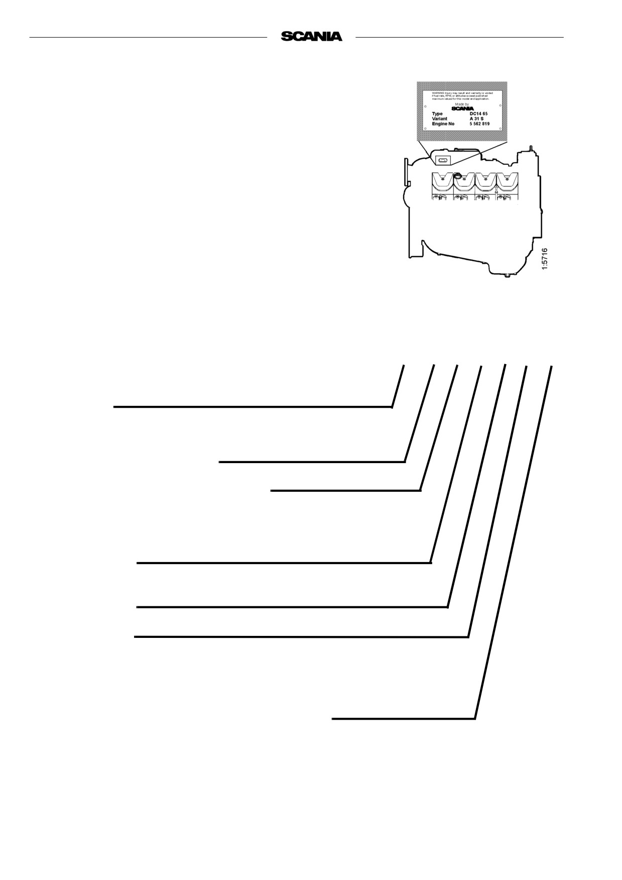
TYPE DESIGNATIONS
The engine designation indicates, in the form of a code, the type of engine, its
size and intended use, etc.
The type designation and engine serial number are indicated on a type plate
affixed to the right-hand side of the engine.The engine number is also stam-
ped in the engine block beside the first cylinder head.
Engines that are certified regarding smoke and emissions are fitted with a cer-
tification plate specifying the documents they conform to. The plate is fitted
to rocker cover number four from the front on the right hand side.
DI
14 74 M 31 S LR
Type
DI
Turbocharged diesel engine with liquid-cooled charge air cooler
Displacement in whole dm3
Performance and certification code
Indicates, together with the application code, the normal gross engine
output.
The actual output setting of the engine is indicated on the engine card.
Application
M For marine use
Variant 01-99
Governor type
D Electronically controlled auxiliary governor
S
RSV, all-speed and single-speed governor
T
RQ, single-speed governor
Classification society (applies to classed engines)
ABS American Bureau of Shipping
BV Bureau Veritas
GL Germanischer Lloyd
LR Lloyd’s Register of Shipping
DNV Dwt Norske Veritas
RINA Registro Italiano Navale
SjöV Sjöfartsverket
10
22
5
3
10
1
6
12
19
23 22
2
21
22
20
13
7
4
22
8
9
24
17
18
9
15 14
11
9
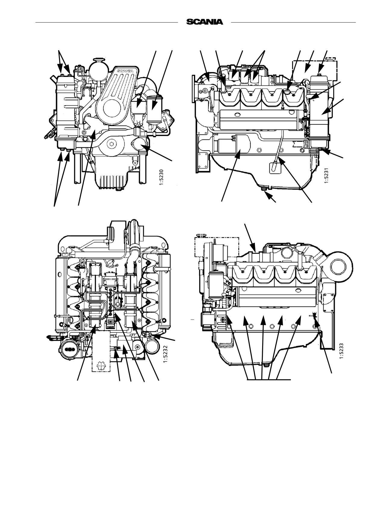
The drawings illustrate a common type of DI14 engine.
Your engine may have other equipment not shown here.
1. Type designation plate
10. Turbocharger
19. Oil filling
2. Engine number,
11. Injection pump
20. Sea water pump
stamped in engine block
12. Fuel filter
21. Heat exchanger
3. Oil cooler
13. Starter motor
22. Protective anodes
4. Oil dipstick
14. Alternator
23. Exp. tank with pressure cap
5. Oil cleaner
15. Fan belt adjustment
24. Oil pressure monitor
6. Oil filter, turbo
16. Inspection hatch, coolant
7. Draining, engine oil
pump
8. Coolant pump
17. Inspection holes, engine block
9. Charge air cooler
18. Draining, coolant
11
STARTING AND RUNNING
AT FIRST START
Coolant composition:
When the engine is started for the first time, follow the maintenance points
listed under "First start" in the maintenance schedule, see page 19.
If there is a danger of freezing:
Since the points are important for satisfactory operation of the engine right
minimum 30% glycol by volume
from the outset, they are also listed below.
maximum 60 % glycol by volume
1. Checking the oil level (see page 21).
8. Checking the coolant (see page 26).
If there is no danger of freezing:
The coolant should contain corrosion inhibitor to protect the cooling
7-12% by volume
system from corrosion.
Scania Anti-corrosive
If there is a danger of freezing:
(no glycol)
- Only anti-freeze glycol should be used in the coolant as protection
against corrosion. We recommend only nitrite-free anti-freeze glycol
with the following supplier designations:
BASF G48-24 or BASF D542
- The concentration of glycol should be 30 - 60% by volume depending
Ethylene glycol and corrosion
on the ambient temperature. 30% glycol by volume provides anti-freeze
inhibitor, if swallowed can be
protection down to -16 °C. See page 26.
fatal.
- The concentration of glycol should be 30 - 60% by volume depending
Avoid contact with the skin.
on the ambient temperature. A content of 30 % by volume provides pro-
tection down to -16 °C. See page 26.
- Never top up with only water or only glycol. Fluid losses must always
be replaced with pre-mixed coolant having the same glycol concentra-
tion as that in the engine. If the glycol content drops, both anti-freeze
The recommended glycol must
protection and protection against corrosion are impaired.
not be mixed with glycol having
Note A glycol concentration below 30% by volume will not provide suf-
nitrite-based anti-corrosive.
ficient protection against corrosion. Glycol concentrations higher
than 60% do not improve anti-freeze protection and have a nega-
tive effect on engine cooling capacity.
If there is no danger of freezing:
- Only Scania Anti-corrosive should be used in the coolant as protection
The use of too much Scania
against corrosion. The correct corrosion inhibitor content is 7-12% by
Anti-corrosive as mixed with
volume and must never be less than 7% by volume. The inhibitor in Sca-
nia Anti-corrosive is free of nitrite.
glycol may cause deposits.
- First filling: Fill the cooling system with water + 10% by volume of
Scania Anti-corrosive. Use drinkable water with a pH value of 6 - 9.
- Never top up with only water or only anti-corrosive! Fluid losses
must always be replaced with premixed coolant:
water + 10 % by volume of Scania Anti-corrosive.
If a coolant filter has been fitted
Coolant filter (not standard equipment)
it must not contain inhibitor.
Only coolant filter without inhibitor may be used. The use of coolant filters
increases the life of the coolant and reduces the risk of deposition corrosion.
12
14. Checking the fuel level (see page 35).
17. Checking theelectrolyte level in batteries (see page 37).
18. Checking the state of charge in batteries (see page 37).
20. Checking the coolant level monitor (see page 38).
Immobilise the starting device
21. Checking the temperature monitor (see page 39).
when working on the engine.
If the engine starts out of
22. Checking the oil pressure monitor (see page 40).
control, there is a
23. Checking stop feature (see page 40).
SERIOUS RISK
24. Checking v-belt tension (see page 42).
OF INJURY.
CHECKS BEFORE RUNNING
Before running, ”Daily maintenance” as described in the maintenance sche-
dule should be carried out, see page 19.
STARTING THE ENGINE
If the fuel tank has been run dry or if the engine has not been used for a long
time, bleed the fuel system, see page 35.
Only start the engine in a
properly ventilated area.
Out of consideration for our common environment, your new Scania engine
has been designed to use a smaller amount of fuel when starting. Using
When operating the engine in
unnecessarily large amounts of fuel when starting the engine always results in
an enclosed area, an effective
the discharge of unburnt fuel.
extraction device for exhaust
- Engines with mechanical stop control: Set the stop control to operating
gases and crankcase gases
position.
must be used.
- Open fuel valve (if fitted).
- Declutch the engine (does not apply to engines with fixed clutch, e.g.
gensets).
- Engines with battery master switch: Switch on the power using the bat-
tery master switch.
- Set the speed control to raised idling. (Does not apply to gensets)
Never use starting spray or
similar as a starting aid.
- Start the engine.
An explosion may occur in the
Starting at low temperatures
intake pipe, which could cause
Local environmental requirements must be complied with. Starting aids,
personal injury.
engine heaters and/or flame start devices should be used to avoid starting
problems and white smoke.
To limit white smoke, the engine should be run at low speed and under mode-
rate load. Avoid running it longer than necessary at idling speed.
13
At temperatures below 0 °C:
Note Only use starting aids recommended by Scania.
- The starter motor may only be used for 30 seconds at a time. After that
time it must rest for 2 minutes.
If the engine has flame start:
- Operating flame start without timer relay: Press the control button,
which also acts as a pre-glow button (max. 20 seconds). The glow plug
continues to glow as long as this button is depressed after the engine has
started. Maximum time is 5 minutes.
Maximum starter engagement
- Operating flame start with timer relay: Press the pre-glow button
time is 30 seconds. Risk of
(a maximum of 20 seconds). Release it when the engine starts. The timer
overheating. Allow starter to
relay keeps the glow plug glowing for 5 minutes. If a shorter glow time
cool for 2 minutes after a
is required, press the release button. The key must be set to the
starting attempt before
0 position if the start attempt fails.
cranking again.
Note If the engine is equipped with an INTERLOCK switch, this
switch should be depressed and held down until the oil pressure
has reached a sufficiently high level.
- Generator sets should be operated under load immediately after starting
to avoid the risk of white smoke. This applies in particular to engines
that have been installed without aids for heating or applying a basic
load.
- Set the appropriate idle speed before the engine reaches 1,000 rpm (does
not apply to gensets).
- Warm up the engine with a light load. A light load on a cold engine
gives better combustion and faster heating than warming up with no
load.
14
RUNNING
Check instruments and warning lamps at regular intervals.
Speed
The Scania tachometer is divided into sectors of different colours, as follows.
0 - 500 rpm
red area:
prohibited engine speed, passed when
stopping and starting.
500 - 700 rpm
yellow area:
low idle.
700 - 2200 rpm
green area:
normal operating speed.
Highest torque and lowest fuel consum
tion at 1400 - 1600 rpm. Low operatin
speed gives less engine wear.
2200 - 2600 rpm
yellow/
unsuitable operating speed. May occur
green
when switching off.
striped:
2600 - 3000 rpm
red area:
prohibited engine speed
Coolant temperature
Correct coolant temperature during operation:
70 - 93 °C for system at atmospheric pressure.
70 - about 100 °C for system with positive pressure.
High coolant temperature leads to engine damage. Reduce the load on the
engine in order to lower the temperature. If the temperature does not drop,
stop the engine and look for the fault.
During long periods of operation with very low power take-off, the engine
may have difficulty in reaching 70 °C. However, if the load is increased, tem-
perature will rise.
15