Seat Toledo (2019 year). Manual in english - page 15
 

  Index      Manuals     Seat Toledo (2019 year). Manual in english


Search            copyright infringement  


Content      ..     13      14      15      16     ..


Seat Toledo (2019 year). Manual in english - page 15


Towing bracket device

Clamping bush
Clamping bush cap
Ball head cover
Ball-headed bar
Locking balls
Centred
Red marking on the manual regulator
Manual regulator
Key
Key slot cover
Red marking on the manual regulator
White marking on the ball-headed bar

Note

Contact an Authorised Service Partner if
you lose your key.

3

4

5

6

7

8

9

10

11

12

13

14

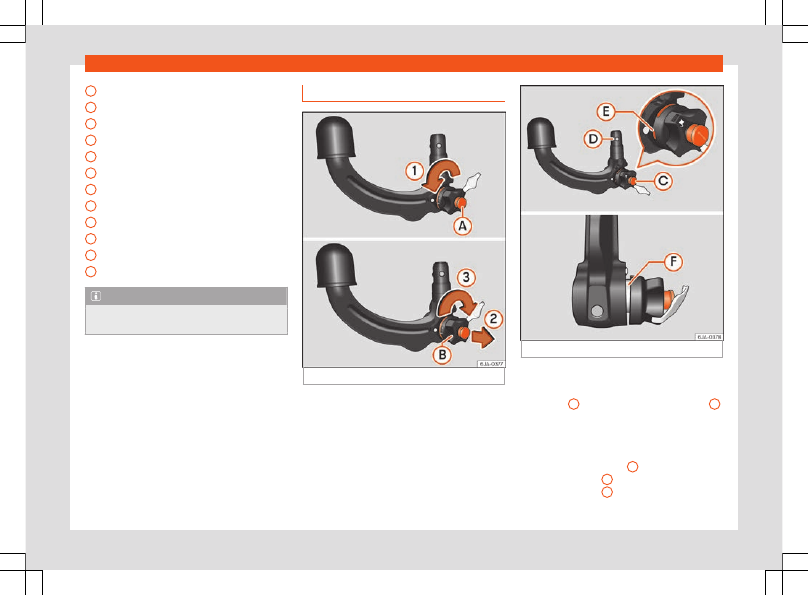
Placing in service position

Fig. 234 

Placing in service position.

Fig. 235 

Service position.

Before assembling, place the ball-headed
bar in service position.

Turn key 

A

 fully in the direction of arrow 

1

››› 

Fig. 234

.

Hold the ball-headed bar with your left
hand.

Pull manual regulator 

B

 outward in the di-

rection of arrow 

2

 and turn it fully in the di-

rection of arrow 

3

.

»

235

Driving

The manual regulator will remain in this posi-
tion.

Service position


››› 

Fig. 235

Key 

C

 is in an open position – the key ar-

row points to the “unlocked” symbol. The key
cannot be removed from the key slot.

The 

D

 locking balls may be fully inserted

into the body of the ball-headed bar by ap-
plying some pressure.

The red 

E

 marking on the manual regula-

tor points towards the white marking on the
ball-headed bar.

Between the manual regulator and the

body of the ball-headed bar there is a clearly
visible space of approximately 4 mm 

F

.

Once the ball-headed bar has been posi-
tioned like this, it will be ready to be placed in
the clamping bush.

WARNING

Do not use the ball-headed bar if it cannot
be correctly placed in the service position.

CAUTION

The key cannot be removed from the man-
ual regulator key slot when it is in the serv-
ice position.

Assembly of the ball-headed bar

Fig. 236 

Placing the ball-headed bar/locking

and removing the key.

Fig. 237 

Placing the key slot cover.

Remove the cap from the clamping bush 

4

››› 

Fig. 233

 by pulling downwards.

Place the ball-headed bar in the service
position 

››› 

page 235

.

Hold the ball-headed bar from underneath

››› 

Fig. 236

 and push it into the clamping

bush as far as possible until you hear it click
into place 

››› 

.

The manual regulator 

A


automatically

turns in the opposite direction, adjusting to
the ball-headed bar 

››› 

.

Switch off the manual regulator lock with
key 

B

 by turning the key fully to the right in

the direction of arrow 

1

 – the arrow in the

key displays the “locked” symbol.

Remove the key in the direction of arrow 

2

.

Place cover 

C

 over the manual regulator

lock in the direction of arrow 

3


››› 

Fig. 237

.

236

Towing bracket device

Verify the correct placement of the ball-
headed bar 

››› 

page 237

.

WARNING

Do not hold the manual regulator with

your hand when fitting the ball-headed bar
since you could sustain injuries to your fin-
gers.

When mounting the ball-headed bar, al-

ways lock it with a key and remove the key
from the slot.

The ball-headed bar must not be in the

service position with the key in the key slot.

If the ball-headed bar is not placed in the

service position you will not be able to
place it in the clamping bush.

CAUTION

When removing the key, always place the
cover over the key slot of the manual regu-
lator to prevent dirt from entering.

Note

Once removed, place the clamping bush
cap in an appropriate location in the boot.

Verification of correct placement

Fig. 238 

Correct placement of the ball-head-

ed bar.

Before using the ball-headed bar, ensure it is
correctly fitted.

Ensure that:

The ball-headed bar does not come out of

the clamping bush in a “jerky” manner.

The red mark 

A


››› 

Fig. 238

 on the manual

regulator signals toward the white mark on
the ball-headed bar.

The manual regulator is adjusted to the

ball-headed bar, leaving no space between
them.

The regulator is locked and the key has

been removed.

Cover 

B

 has been placed over the manual

regulator lock.

WARNING

Only use the towing bracket device when
the ball-headed bar is properly fitted!

237

Driving

Disassembly of the ball-headed
bar

Fig. 239 

Remove the key slot cover/unlock

with the key.

Fig. 240 

Unblock the ball-headed bar.

Remove cover 

A

 from over the regulator

key slot in the direction of arrow 

1

››› 

Fig. 239

.

Insert key 

B

 in the key slot.

Open the manual regulator lock by turning
key 

B

 fully to the left in the direction of ar-

row 

2

. The arrow on the key points to the

“unlocked” symbol.

Hold the ball-headed bar from underneath

››› 

Fig. 240

 and remove manual regulator

C

 with your other hand in the direction of

arrow 

3

.

Turn the removed regulator fully in the di-
rection of arrow 

4

 and hold it firmly in this

position.

Remove the ball-headed bar from the
clamping bush, pulling downward in the di-
rection of arrow 

5

.

The ball-headed bar should be placed in the
service position so that it is ready to be inser-
ted into the clamping bush 

››› 

.

Place the cover over the clamping bush 

4

››› 

Fig. 233

.

WARNING

Never leave the ball-headed bar unse-

cured in the boot. It could be damaged in
the event of sudden braking, putting the
safety of passengers at risk!

Never disassemble the ball-headed bar

with the trailer still hitched.

CAUTION

If you do not turn the manual regulator

fully, it will return to its original position
when the ball-headed bar is removed. The
manual regulator will be stuck to the ball-
headed bar and you will not be able to put
it in the service position. Therefore, before
you assemble it again, you must place the
ball-headed bar in this position.

After disassembly, place the cap on the

clamping bush’s orifice. This way you will
prevent dirt from entering the clamping
bush.

Note

Before disassembling the ball-headed

bar, we recommend placing the cover on
the ball head.

238

Towing bracket device

Clean the ball-headed bar thoroughly

before returning it to the on-board toolbox.

Use and maintenance

Cover the clamping bush with the cap to pre-
vent dirt from entering.

Before hooking on the trailer, check the ball
head and, if necessary, lubricate it with ade-
quate lubricant.

Place the protective cover over the ball head
when storing the bar. This way, you will avoid
getting the boot dirty.

If it gets dirty, clean and dry the clamping
bush thoroughly with an appropriate product.

CAUTION

The top part of the clamping bush opening
is lubricated. Be careful not to remove this
lubrication.

239

Practical tips

Practical tips

Accessories and modifi-
cations to the vehicle

Accessories and modifica-
tions to the vehicle

Accessories, replacement parts
and repair work

If you wish to retrofit accessories in the vehi-
cle, or if a part of the vehicle has been re-
placed by a new part or technical modifica-
tions are required, the following instructions
must be taken into account:

Before

 purchasing accessories or spare

parts and 

before

 making technical modifica-

tions, always request advice from an Author-
ised SEAT dealer 

››› 

.

In the event that technical modifications

are carried out on the vehicle, the instructions
and regulations specified by the company,
SEAT, must be observed.

No damage will be caused to the vehicle if
the established procedures are respected,
which guarantees safe driving and operation.
After the modifications are carried out, the
vehicle will comply with the restrictions and

regulations of the highway code. More infor-
mation can be obtained at an Authorised
SEAT dealer, where all jobs required can be
carried out appropriately.

Vehicle improvements and modifications

The owner must keep the technical docu-
mentation regarding the modifications car-
ried out on the vehicle so it can be handed
over to those responsible for processing end-
of-life vehicles. This ensures end-of-life pro-
cessing of the vehicle, while protecting the
environment.

Work done on the electrical components and
software can cause disruption in operations.
Due to the interconnection of electronic com-
ponents, their malfunction can also impair
systems that are not directly affected. This
can adversely affect reliability of the vehicle,
and can produce excessive wear of the parts.

Damage caused by technical modifications
that are not made with the consent of SEAT
will be excluded from the warranty – see war-
ranty certificate.

WARNING

Jobs or modifications unduly carried out

on your vehicle can cause disruption to op-
erations - Risk of accident!

We recommend that you use only ex-

pressly authorised SEAT Accessories and
SEAT Original Spare Parts for your vehicle.

The reliability, safety and compatibility
with your vehicle of SEAT original spare
parts and accessories has been verified.

Despite the continuous observation of

the market, we cannot judge nor guarantee
the suitability of other products for your ve-
hicle, be they authorised products or prod-
ucts approved by a state testing facility.

Note

SEAT original spare parts and accessories
can be purchased at authorised SEAT deal-
ers where the purchased parts can also be
fitted.

Modifications and effects of the
airbag system

In the adjustment and modification, respect
the SEAT directive.

Modifications and corrections of the front
bumper, doors, front seats, roof or bodywork
must be carried out at authorised SEAT work-
shops. Components of the airbag system can
be found in these parts of the vehicle.

WARNING

Airbag modules must never be repaired.

They must be replaced.

Never fit components of the airbag sys-

tem removed from old vehicles or those

240

Checking and refilling levels

originating from a recycling process in the
vehicle.

The modification of the suspension of the

vehicle wheels, including the use of non-
permitted combinations of tyres and rims
can alter the operation of the airbag sys-
tem and increase the risk of serious or fatal
injuries in an accident.

During all jobs on the airbag system, in

addition to the removal and fitting of parts
of the system in the course of other repair
jobs, parts of the airbag system can be
damaged. Therefore in the event of an ac-
cident, this may cause the airbags to acti-
vate incorrectly or not activate at all.

Radio and aerial reception

In vehicles factory-fitted with an audio or
navigation system, the aerial may be instal-
led in different places:

inside the rear window next to the heating

elements,

on the roof of the vehicle.

Checking and refilling lev-
els

Fuel

Refuelling

Fig. 241 

Rear part of the vehicle, right side:

tank lid/tank lid with unscrewed cap.

Read the additional information carefully

››› 

page 41

The correct type of fuel for your vehicle is in-
dicated on a sticker on the inside of the fuel
tank flap, along with the tyre size and pres-
sure 

››› 

Fig. 241


.

Vehicles with a fuel cap with key

Press the flap in the direction of the arrow

1


››› 

Fig. 241

.

Open the cover in the direction indicated
by the arrow 

2

.

Hold onto the fuel tank cap with one hand
and unlock it using the ignition key, turning it
anti-clockwise.

Unscrew the tank cap anti-clockwise and
place it on top of the tank flap 

››› 

Fig. 241

.

Insert the pump nozzle into the fuel feed
tube as far as it will go.

The fuel tank is full as soon as the automatic
filler nozzle cuts out 

››› 

.

Remove the pump nozzle from the fuel feed
tube and place it back on the pump.

Screw the tank cap clockwise until it clicks
into place.

Hold onto the fuel tank cap with one hand
and lock it using the ignition key, turning it
clockwise.

Press the tank flap with your hand to close
it.

»

241

Practical tips

Check that the fuel flap is correctly closed.

Vehicles with a keyless fuel cap (the side
flap will unlock using the central locking
system)

Once the vehicle has been unlocked using
the central locking button, press the fuel
flap in the direction of the arrow 

1

››› 

Fig. 241

.

Open the cover in the direction indicated
by the arrow 

2

.

Unscrew the tank cap anti-clockwise and
place it on top of the tank flap 

››› 

Fig. 241

.

Insert the pump nozzle into the fuel feed
tube as far as it will go.

The fuel tank is full as soon as the automatic
filler nozzle cuts out 

››› 

.

Remove the pump nozzle from the fuel feed
tube and place it back on the pump.

Screw the tank cap clockwise until it clicks
into place.

Close the tank flap. Make sure you hear it
click into place.

Check that the fuel flap is properly closed.

WARNING

Observe all relevant statutory regulations
on transporting spare fuel canisters. For
safety reasons, we do not recommend car-
rying a spare canister in the vehicle. The
canister could be damaged in an accident
and fuel may leak. Risk of fire!

CAUTION

Switch off the auxiliary heater (heater

and independent heater) before filling the
tank.

The fuel tank is full as soon as the auto-

matic filler nozzle cuts out. Do not continue
filling, as this will fill the expansion cham-
ber.

Never completely empty the tank! An ir-

regular fuel supply can cause ignition
faults, which can result in damage to a sub-
stantial amount of engine parts and the ex-
haust system.

If any fuel is spilt onto the paintwork of

the vehicle, it should be removed immedi-
ately. Risk of damage to paintwork!

Note

There is no emergency mechanism for the
manual release of the fuel tank flap. If nec-
essary, request assistance from special-
ised personnel.

Note

The fuel tank capacity is around 55 litres,
of which 7 litres are the reserve.

Identification of the fuel

1)

Fig. 242 

Identification of fuels according to

European Union (EU) Directive 2014/94/

Fuels are identified with different symbols.
Depending on the fuel, the different symbols
are on the pump and the tank lid of your vehi-
cle. The identification serves to prevent con-
fusion when choosing the fuel.

Petrol

 with ethanol (“E” stands for 

E

tha-

nol). The number indicates the percent-
age of ethanol in the petrol. “E5” means,
for example, an ethanol ratio of 5% max.

1

1)

Depending on country

242

Checking and refilling levels

Diesel

 with biodiesel (“B” stands for 

B

io-

diesel). The number indicates the per-
centage of biodiesel in the diesel. “B7”
means, for example, a proportion of bio-
diesel of max. 7%.

Natural gas

: “CNG” means 

C

ompressed

N

atural 

G

as.

Type of petrol

3

 Applies to vehicles: with petrol engine

The correct grade of petrol is listed inside the
fuel tank flap.

The vehicle is equipped with a catalytic con-
verter and must only be run on 

unleaded

petrol

. The petrol must comply with the

standard EN 228 and be 

sulphur-free

. Fuels

with a 10% ethanol ratio can be refuelled
(E10)

1)

. The types of petrol are differentiated

by using the 

octane numbers (RON)

 or via

the 

anti-knock index (AKI)

.

The following pieces of text show the infor-
mation included in the corresponding stickers
on the tank lid (examples):

2

3

Super unleaded petrol 95 octane petrol or
normal 91 octane petrol at least

We recommend refuelling with super 95 oc-
tane petrol (91 AKI). If not available: normal 91
octane petrol (87 AKI) (with a slight power
loss).

Super unleaded petrol, 95 octanes at
least

You should use super 95 octane petrol (91
AKI) at least.

If super is not available, 

if necessary

, use nor-

mal 91 octane petrol (87 AKI). In this case only
use moderate engine speeds and a light
throttle. Refuel with super as soon as possi-
ble.

Unleaded super plus 98 octane petrol or
super 95 octane petrol at least

We recommend refuelling with super plus 98
octane petrol (93 AKI). If not available: super
95 octane petrol (91 AKI) (with a slight power
loss).

If super is not available, 

if necessary

, use nor-

mal 91 octane petrol (87 AKI). In this case only
use moderate engine speeds and a light
throttle. Refuel with super as soon as possi-
ble.

CAUTION

Fuels high percentage of ethanol, e.g.

E30 - E100 button must not be used. The
fuel system would be damaged. Exception:
vehicles with Totalflex engine 

››› 

page 244,

Ethanol fuel

.

A single refuelling with leaded fuel or

other metal additives entails a permanent
deterioration of the effectiveness of the
catalytic converter.

Only use fuel additives that have been

approved by SEAT. The products that con-
tain substances to increase the octane rat-
ing or decrease knocking may contain met-
al additives that damage the engine and
catalytic converter. This type of products
must not be used.

Do not use fuels shown in the pump as

containing metals. LRP (

lead replacement

petrol

) fuels contain high concentrations of

metal additives. Risk of engine damage!

High engine speed and full throttle can

damage the engine when using petrol with
an octane rating lower than the correct
grade for the engine.

Note

Fuel with an octane rating higher than the

one required by the engine can be used.

»

1)

Follow the regulations of the country you are

driving in.

243

Practical tips

In countries in which there is no sulphur-

free fuel, it is also allowed to use low sul-
phur content fuel.

Ethanol fuel

3

 Applies to vehicles: with Totalflex engine

You can recognise vehicles with Totalflex en-
gines

1)

 by label on the fuel tank lid with with

the marking “Petrol/ethanol”.

Vehicles with Totalflex engine can run with
unleaded petrol (95 octane / 91 AKI) accord-
ing to ANP No. 57 and with fuels with any high
percentage of ethanol. The vehicle is refuel-
led in the same way as petrol refuelling.

Also consider that 

››› 

page 243, Type of pet-

rol

Note

SEAT recommends filling the tank exclu-
sively with petrol every 10,000 km to de-
crease impurities that using E100 ethanol
fuel might have left in the engine.

Diesel

3

 Applies to vehicles: with diesel engine

Please note the information on the inside of
the fuel tank flap.

We recommend you use 

Diesel

 according to

standard EN 590.

The diesel can thicken at very low tempera-
tures, thus affecting the start or operation of
the engine. To ensure that you can continue
to use your vehicle as usual, the diesel sold in
gas stations is provided -depending on the
station- with fluidity when cold. Ask the em-
ployee of the petrol station whether their die-
sel is suitable for use in winter and if it is suited
for current and future temperatures.

Water in the fuel filter

2)

If your vehicle has a diesel engine and is
equipped with a 

fuel filter with a water sep-

arator

, the instrument panel may display the

following warning: 


Water in the fuel

filter.

 If this is the case, take the vehicle to

a specialised workshop so that they can
drain the fuel filter.

CAUTION

Never use of FAME (biodiesel), petrol,

heating oil, other fuels or thinning agents
as they can cause severely damage the
fuel system and the engine.

If the wrong fuel has been filled, do not

start the engine under any circumstances.
Risk of damaging the fuel system and the
engine! Obtain technical assistance.

Engine compartment

Working in the engine compart-
ment

Read the additional information carefully

››› 

page 13

Always be aware of the danger of injury
and scalding as well as the risk of acci-
dent or fire when working in the engine
compartment, e.g. when checking and re-
filling fluids. Therefore, always observe
the warnings and follow all general safety
precautions. The engine compartment is a
dangerous area

.

1)

This motor is only available in some markets.

2)

Valid for the market: Algeria.

244

Checking and refilling levels

WARNING

Never open the bonnet if you see steam,

smoke or coolant escaping from the engine
compartment. Risk of scalding! Wait until
no steam or coolant can be seen before
opening the bonnet.

Switch off the engine and remove the key

from the ignition.

Engage neutral in vehicles with manual

gearbox and move the selector lever to po-
sition P in vehicles with automatic gearbox.

Apply the handbrake firmly.

Wait for the engine to cool down.

For safety reasons, the bonnet must al-

ways be closed when the vehicle is moving.
Therefore, after closing the bonnet always
check that it is properly secured.

Should you notice that the bonnet is not

safely secured when the vehicle is moving,
stop the vehicle immediately and close the
bonnet properly. Risk of accident!

Keep children away from the engine

compartment.

Do not touch hot engine parts. Risk of

burns!

Never spill fluids on hot engine compart-

ments. These fluids can cause a fire (e.g.
antifreeze in coolant)!

Take care not to cause short circuits in

the electrical system, especially when
working on the battery.

Never touch the radiator fan when the en-

gine is hot. The fan may start running sud-
denly!

Never cover the engine with additional in-

sulating materials such as a blanket. Risk of
fire!

Do not unscrew the cap on the coolant

expansion tank when the engine is hot. The
cooling system is under pressure!

Protect face, hands and arms from any

hot steam or hot coolant released by cov-
ering the cap with a large, thick rag when
opening the expansion tank.

Do not leave any objects, such as cloths

or tools, in the engine compartment.

When working underneath the vehicle,

secure it so that it cannot roll away and
support it safely on suitable supports. The
hydraulic jack is not sufficient for this pur-
pose. Risk of injuries!

If any tests have to be performed with the

engine running, there is an extra safety risk
from rotating parts, such as the drive belt,
alternator and radiator fan, etc., and from
the high-voltage ignition system. You
should also note the following:

Never touch the electrical wiring of the
ignition system.

Keep away from moving engine parts
when wearing jewellery, loose clothing
or long hair. Risk of fatal injuries! All
jewellery must be removed, hair tied
back and close-fitting clothing worn.

Observe the following additional warn-

ings if work on the fuel system or the elec-
trical system is necessary.

Always disconnect the battery from the
on-board network.

Do not smoke.

Never work near naked flames.

Always keep an approved fire extin-
guisher immediately available.

CAUTION

When topping up fluids, make sure the

correct fluid is put into the correct filler
opening. Otherwise this can cause serious
malfunctions or engine damage!

Never open the bonnet using the release

catch. Risk of damage!

For the sake of the environment

Due to the environmentally-friendly dis-
posal of fluids, the equipment necessary
and the knowledge required, let an author-
ised SEAT dealer change fluids during serv-
ice inspections of the vehicle.

Note

Please contact an authorised SEAT deal-

er with any doubts regarding fluids.

Fluids of the correct specifications can

be acquired from the selection of SEAT
Original Accessories.

245

Practical tips

Checking levels

Fig. 243 

Diagram for the location of the various el-

ements.

From time to time, the levels of the different
fluids in the vehicle must be checked. Never
fill with incorrect fluids, otherwise serious
damage to the engine may be caused.

Coolant expansion tank . . . . . . . . . . . . . 249
Window washer water tank . . . . . . . . . . 251
Engine oil filler cap . . . . . . . . . . . . . . . . . . . 248
Engine oil level dipstick . . . . . . . . . . . . . . 248
Brake fluid reservoir . . . . . . . . . . . . . . . . . . 250
Battery . . . . . . . . . . . . . . . . . . . . . . . . . . . . . . . . 251

The checking and replenishment of the serv-
ice fluids are carried out on the components

1

2

3

4

5

6

mentioned above. These operations are de-
scribed in the 

››› 

page 244

.

Overview

You will find further explanations, instructions
and restrictions on the technical specifica-
tions as of 

››› 

page 275

.

Note

The layout of the engine compartment is
very similar to all petrol and diesel engines.

Radiator fan

The radiator is driven by an electric motor
and controlled according to the temperature
of the coolant.

After the engine has been stopped and the
ignition switched off, the radiator fan may
continue running for around 10 minutes.

246

Checking and refilling levels

Engine oil

General notes

The engine comes with a special, multi-grade
oil that can be used all year round.

Because the use of high-quality oil is essen-
tial for the correct operation of the engine
and its long useful life, when topping up or
changing oil, use only those oils that comply
with VW standards.

We recommend that the oil change indicated
in the Maintenance Programme, be per-
formed by a technical service or specialised
workshop.

If the engine oil level is too low

You can get information about the correct en-
gine oil for your vehicle at your specialised
shop. If you have to change your engine oil,
use that oil.

If the recommended engine oil is not availa-
ble, in the event of an emergency you can
add oil once up to a maximum of 0.5 L of the
next oil until the next oil change:

Valid for vehicles with petrol engines:

standard VW 504 00, VW 502 00,
VW 508 00, ACEA C or API SN.

Vehicles with diesel particulate filter*

Only VW 507 00 engine oil, with reduced ash
formation, may be used in diesel engines
equipped with particulate filter. Using other
types of oil will cause a higher soot concen-
tration and reduce the life of the DPF. There-
fore:

Avoid mixing this oil with other engine oils.

Only in exceptional circumstances, if the

engine oil level is too low 

››› 

page 248

 and

you cannot obtain the oil specified for your
vehicle, you can use a small quantity of oil
(once) conforming to the specifications
VW 506 00, VW 506 01, VW 505 00,
VW 505 01 or ACEA B3/ACEA B4 (up to 0.5 l)

››› 

page 42

.

Note

Before a long trip, we recommend finding
an engine oil that conforms to the corre-
sponding VW specifications and recom-
mend keeping it in the vehicle. This way, the
correct engine oil will always be available
for a top-up if needed.

Warning lamp

Flashes red

The information display shows:

Oil pressure. Switch off the engine!
Instruction Manual!


Do not carry on driving!

 Switch off the engine

and check the engine oil level 

››› 

page 248

If the symbol flashes although the oil level is correct,


do not drive on

. Do not even run the engine at

idle speed! Go to a technical service.

It lights up yellow

The information display shows:

Check oil level!

Park the vehicle, stop the engine and check the en-

gine oil level 

››› 

page 248

.

If the bonnet stays open for over 30 seconds, the

warning lamp switches off. If the engine oil is not refil-

led, the warning lamp illuminates again after 100 km
(62 miles).

It flashes yellow

The information display shows:

Oil sensor! Workshop

!If the engine oil level sensor is faulty, The warning
lamp 

 flashes various times after the ignition is

switched on and an audible warning is given. Go to a
technical service.

247

Practical tips

Checking engine oil level

Fig. 244 

Engine oil dipsticks.

Read the additional information carefully

››› 

page 42

The dipstick shows the engine oil level.

››› 

Fig. 244

.

Checking oil level

Park the vehicle on a level surface and en-
sure the engine is at operating temperature.

Switch the ignition off.

Open the bonnet.

Wait a few minutes for the engine oil to flow
back to the sump and remove the dipstick.

Wipe the dipstick with a clean cloth and in-
sert it again as far as it will go.

Then pull the dipstick out again and check
the oil level.

It is normal for the engine to consume a cer-
tain amount of oil. Depending on how you
drive and the conditions in which the vehicle
is used, oil consumption can be up to 0.5 li-
tres per 1,000 km. Oil consumption can also
be higher for the first 5,000 km (3000 miles).

You should therefore check the oil level at
regular intervals, ideally every time you fill the
tank or before setting off on a long trip.

CAUTION

The oil level must never exceed area 

A

.

Risk of damaging the exhaust system!

If the engine oil cannot be topped up un-

der the given conditions, 

 do not drive on!

Stop the engine and seek the professional
assistance of an Official Service, as this
could cause serious damage to the engine.

Topping up engine oil

Check the engine oil level 

››› 

page 248,

Checking engine oil level

.

Unscrew the cap from the filler opening.

Put in the specified grade of oil 0.5 litres at
a time 

››› 

page 247

.

Check the oil level 

››› 

page 248

.

Replace the oil filler cap carefully and push
the dipstick all the way in.

Changing engine oil

Engine oil must be changed with the frequen-
cy indicated in the Maintenance Programme
or according to the service interval indicator

››› 

page 33

.

CAUTION

Do not mix engine oil with additives. Risk of
damage to the engine! Damage caused by
these products is not covered by the war-
ranty.

Note

Wash your skin thoroughly if it comes into
contact with engine oil.

Coolant

Control lamp

It lights up blue

The engine has not yet reached service tempera-

ture

a)

.

Avoid high engine speeds, hard acceleration and
subjecting the engine to high loads.

a)

This does not apply to vehicles equipped with an in-

formative display.

248

Checking and refilling levels

It lights up or flashes red

The coolant temperature is too high or the coolant

level too low.


Do not carry on driving!

 Switch off the engine

and check the coolant level 

››› 

page 249

, and fill it if

necessary 

››› 

page 249

.

The information display shows:

Check coolant! Instruction Manual!

If the coolant is situated in the prescribed
area, the high temperature may be due to a
fault in the cooling system fan. Check the ra-
diator fan fuse and replace it if necessary

››› 

page 45

.

If the warning lamp 

 (red) remains lit up, de-

spite both the coolant level and the radiator
fan fuse being in correct condition, 


stop

the vehicle!

Go to a technical service.

WARNING

Take care when opening the coolant res-

ervoir. When the engine is warm or hot, the
system is pressurised – Danger of burns!
Wait for the engine to cool before opening
the cover.

Do not touch the fan. The fan can switch

on automatically regardless of whether the
ignition is switched on.

Checking coolant level

Fig. 245 

Engine compartment: coolant tank.

Read the additional information carefully

››› 

page 43

The coolant expansion tank is located in the
engine compartment of the vehicle.

Switch the ignition off.

Open the bonnet 

››› 

page 244

.

Read off the coolant level on coolant ex-
pansion tank 

››› 

Fig. 245

. When the engine

is cold, the coolant should be between
marks 

B

 (min.) and 

A

 (max.). When the

engine is hot, it may be slightly above mark

A

 (max.).

If the coolant fluid level in the reservoir is too
low, this will be indicated by the 

 red warn-

ing lamp illuminating on the general dash
panel 

››› 

page 248

. However, we recom-

mend checking the coolant level directly in
the tank.

Coolant fluid loss

Any loss of coolant normally indicates a 

leak

.

It is not sufficient merely to top up the cool-
ant. The cooling system should be inspected
by an Official Service without delay.

CAUTION

In the event of a fault that causes the en-

gine to overheat, contact an authorised
SEAT dealer immediately, as this could
damage the engine.

Anti-freeze that does not correspond to

the correct specification may particularly
affect corrosion protection considerably.

Faults caused by corrosion may lead to

coolant leaks. Risk of serious engine faults!

Topping up the coolant level

Switch the ignition off.

Wait for the engine to cool down.

Cover the cap on the coolant expansion
tank 

››› 

Fig. 245

 with a cloth and 

carefully

unscrew the cap.

Refill the level of coolant.

Screw the cap on again until it clicks into
place.

Do not use a different type of additive if the
prescribed anti-freeze additive is not

»

249

Practical tips

available, in the event of an emergency. In
this case, use only water and bring the cool-
ant concentration back up to the correct lev-
el as soon as possible at an Official Service.

Always top up with unused coolant.

Never fill the coolant tank above mark 

A

(max.) 

››› 

Fig. 245

 ! Excess coolant is forced

out of the cooling system through the over-
pressure valve in the filler cap of the expan-
sion tank when the engine heats up.

WARNING

The anti-freeze additive and, therefore,

the entire coolant, are a health hazard.
Avoid touching the coolant. Coolant fumes
are also a health hazard. For this reason,
always store the coolant additive in a safe
place out of the reach of children. Risk of
poisoning!

If splashed into eyes, rinse immediately

with clean water and seek immediate med-
ical attention.

Seek immediate medical attention if the

coolant is accidentally ingested.

CAUTION

If the coolant cannot be topped up under
the given conditions, 

 do not drive on. We

recommend contacting an authorised SEAT
dealer, as this can damage the engine.

Brake fluid

Checking brake fluid level

Fig. 246 

Engine compartment: coolant tank.

Read the additional information carefully

››› 

page 43

The brake fluid reservoir is located in the en-
gine compartment of the vehicle.

Switch the ignition off.

Open the bonnet 

››› 

page 244

.

Check the brake fluid level in the reservoir

››› 

Fig. 246

. It should be between the “MIN”

and “MAX” marks.

The fluid level drops slightly after a period of
time due to automatic compensation for
brake pad wear. This is quite normal.

However, if the level goes down noticeably in
a short time, or drops below the “MIN” mark,
there may be a leak in the brake system. If the

brake fluid level in the reservoir is too low, this
will be indicated by the warning lamp illumi-
nating on the instrument panel 

››› 

page 200, Control lamps

.

WARNING

If the fluid level has dropped below the

MIN mark, 

 do not continue driving. Risk of

accident! Go to a technical service.

Heavy use of the brakes may cause a va-

pour lock if the brake fluid is left in the
brake system for too long. This would seri-
ously affect the efficiency of the brakes
and the safety of the vehicle.

Changing the brake fluid

Brake fluid absorbs moisture. Therefore, it
gradually absorbs moisture from the atmos-
phere. If the water content in the brake fluid is
too high, the brake system could corrode. The
water content also reduces the boiling point
of the brake fluid.

The brake fluid must comply with one of the
following standards or specifications:

VW 50114

FMVSS 116 DOT4

CAUTION

Brake fluid damages the vehicle paintwork.

250


Content      ..     13      14      15      16     ..