Nissan Silvia. Manual - part 85


  Index      Nissan     Nissan Silvia - Service Manual (2001 year)


Search            


Content   ..  83  84  85  86   ..


Nissan Silvia. Manual - part 85


Removal

NMBR0033

WARNING:

Clean brake pads with a vacuum dust collector to minimize the
hazard of airborne particles or other materials.

FBR012

1.

Drain brake fluid.

2.

Remove the brake pads.

3.

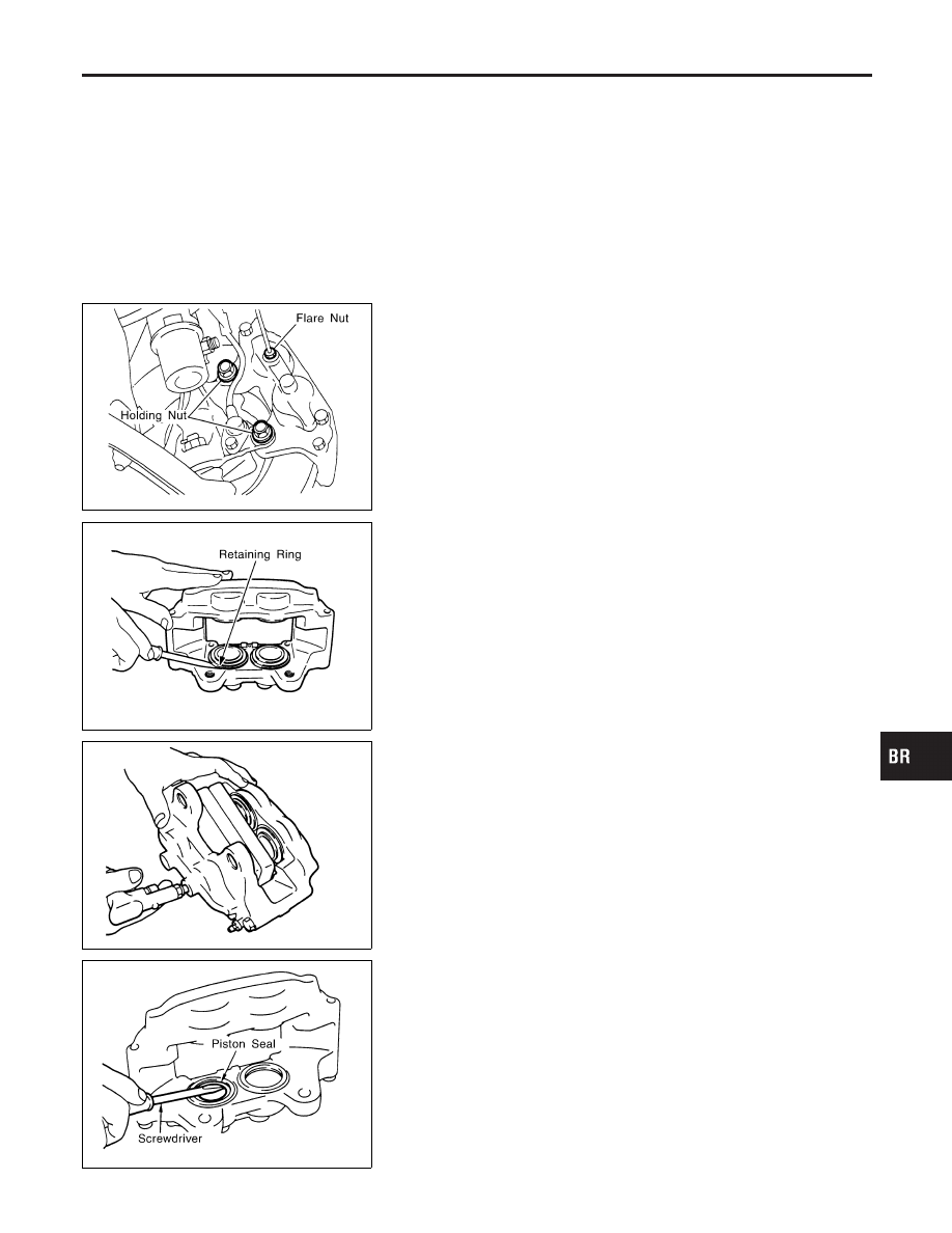
Separate the caliper assembly and the brake tube using a flare
nut spanner.

4.

Remove the caliper holding bolt and then remove the caliper
assembly.

5.

Remove the disc rotor.

FBR013

Disassembly

NMBR0034

1.

Remove the caliper assembly.

2.

Using a screwdriver as shown in the figure to the left, remove
the retaining ring.

FBR014

3.

Insert pieces of wood as shown in the figure to the left and
then, place air into the flare nuts holes and then remove the
piston and the piston boots. At this time should the 4 pistons
not be removed evenly, insert the removed piston inwards
slightly and then blow air into the flare nut holes once more.

4.

Remove the piston boots from the pistons.

FBR015

5.

Using a screwdriver, remove the piston seals.

CAUTION:

Care should be taken not to scratch the inner side of the
cylinder.

GI

MA

EM

LC

EC

FE

CL

MT

AT

PD

AX

SU

ST

RS

BT

HA

SC

EL

IDX

FRONT DISC BRAKE

Removal

BR-23

Inspection

NMBR0035

CALIPER

NMBR0035S01

I

Check dust seals for damage.

I

Check calipers for damage, rust or foreign materials.

I

Check inside surface of cylinder for scoring, rust, wear, dam-
age or foreign materials. Replace if any such condition exists.

I

Eliminate minor damage from rust or foreign materials by pol-
ishing surface with fine emery paper.

CAUTION:

Use brake fluid to clean.

PISTON

NMBR0035S03

Check piston for scoring, rust, wear, damage or foreign materials.
Replace if any condition exists.

CAUTION:

Piston sliding surface is plated. Do not polish with emery
paper even if rust or foreign materials are stuck to sliding
surface.

PAD PIN AND CLIPS

NMBR0035S04

Check for wear, cracks deformation, deterioration, rust or other
damage. Replace if any such condition exists.

SBR019B

ROTOR

NMBR0035S02

Runout

NMBR0035S0201

1.

Secure rotor to wheel hub with at least two nuts.

2.

Check runout using a dial indicator.

Make sure that wheel bearing axial end play is within the
specifications before measuring. Refer to AX-3, 
“Front Wheel
Bearing”.

Measuring point:

Inspect 10 mm (0.39 in) from the outer perimeter of
the disc.

Maximum runout:

0.07 mm (0.0028 in)

3.

If the runout is out of specification, find minimum runout posi-
tion as follows:

a.

Remove nuts and rotor from wheel hub.

b.

Shift the rotor one hole and secure rotor to wheel hub with
nuts.

c.

Measure runout.

d.

Repeat steps a. to c. so that minimum runout position can be
found.

4.

If the runout is still out of specification, turn rotor with on-car
brake lathe (“MAD, DL-8700”, “AMMCO 700 and 705” or
equivalent).

FRONT DISC BRAKE

Inspection

BR-24

SBR020B

Thickness

NMBR0035S0202

Thickness variation (At least 8 positions):

Maximum 0.02 mm (0.0008 in)

If thickness variation exceeds the specification, turn rotor with on-
car brake lathe.

Rotor repair limit:

28.0 mm (1.1024 in)

Assembly

NMBR0036

CAUTION:

Do not use Nissan Rubber Grease when assembling.

FBR016

1.

Apply Nissan Rubber Lubricant to the piston seals and then
install them to the cylinder body.

FBR017

2.

Apply DOT 3 brake fluid or Nissan Lubricant to the piston
boots, and then cover the end of the piston with the piston
boots. Make sure that the lip on the piston side of the piston
boots goes into the groove of the piston.

3.

Push the piston into the cylinder body by hand, and then make
sure that the lip on the piston boots goes into the groove on
the piston.

CAUTION:

Take care not scratch the inside of the cylinder wall when
pushing the piston into the cylinder.

GI

MA

EM

LC

EC

FE

CL

MT

AT

PD

AX

SU

ST

RS

BT

HA

SC

EL

IDX

FRONT DISC BRAKE

Inspection (Cont’d)

BR-25

FBR018

4.

Set the retaining ring to the piston boots.

CAUTION:

Make sure that the boots are fitted into the groove of the cyl-
inder body properly.
5.

Install the caliper assembly.

FBR012

Installation

NMBR0037

1.

Install the disc rotor.

CAUTION:

Do not get any water or oil on the installation area of the
knuckle, caliper and screw installation areas, holding bolts
and the washers.
2.

Install the caliper assembly and then tighten the holding bolts
to the specified torque.

3.

Install the brake tube to the caliper assembly and then tempo-
rarily tighten with the flare nut.

4.

Tighten to the specified torque using the flare nut.

Tightening torque: Refer to BR-9.

5.

Install the brake pads.

6.

After installing the caliper assembly, replace with new brake
fluid and bleed any air in the system. Refer to BR-8.

Brake Burnishing Procedure

NMBR0088

When experiencing soft brake pedal feel at very low mileage, or
after replacing the rotor, burnish the brake pad contact surfaces
according to the following procedures.

CAUTION:

Only perform this procedure under safe road and traffic con-
ditions. Use extreme caution.
1.

Drive the vehicle on a straight smooth road at 50 km/h (31
MPH).

2.

Use medium brake pedal/foot effort to bring the vehicle to a
complete stop from 50 km/h (31 MPH). Adjust brake pedal/foot
pressure such that vehicle stopping time equals 3 to 5 sec-
onds.

3.

To cool the brake system, drive the vehicle at 50 km/h (31
MPH) for 1 minute without stopping.

4.

Repeat steps 1 to 3 10 times or more to complete the burnish-
ing procedure.

FRONT DISC BRAKE

Assembly (Cont’d)

BR-26


Content   ..  83  84  85  86   ..