Nissan Almera Tino V10 (2001 year). Manual - part 165


  Index      Manuals     Nissan Almera Tino V10 (2001 year) - Service and Repair Manual


Search            copyright infringement  


Content      ..     163      164      165      166     ..


Nissan Almera Tino V10 (2001 year). Manual - part 165


YHA349

TROUBLE DIAGNOSES

Wiring Diagram — A/C, M — (Cont’d)

HA-34
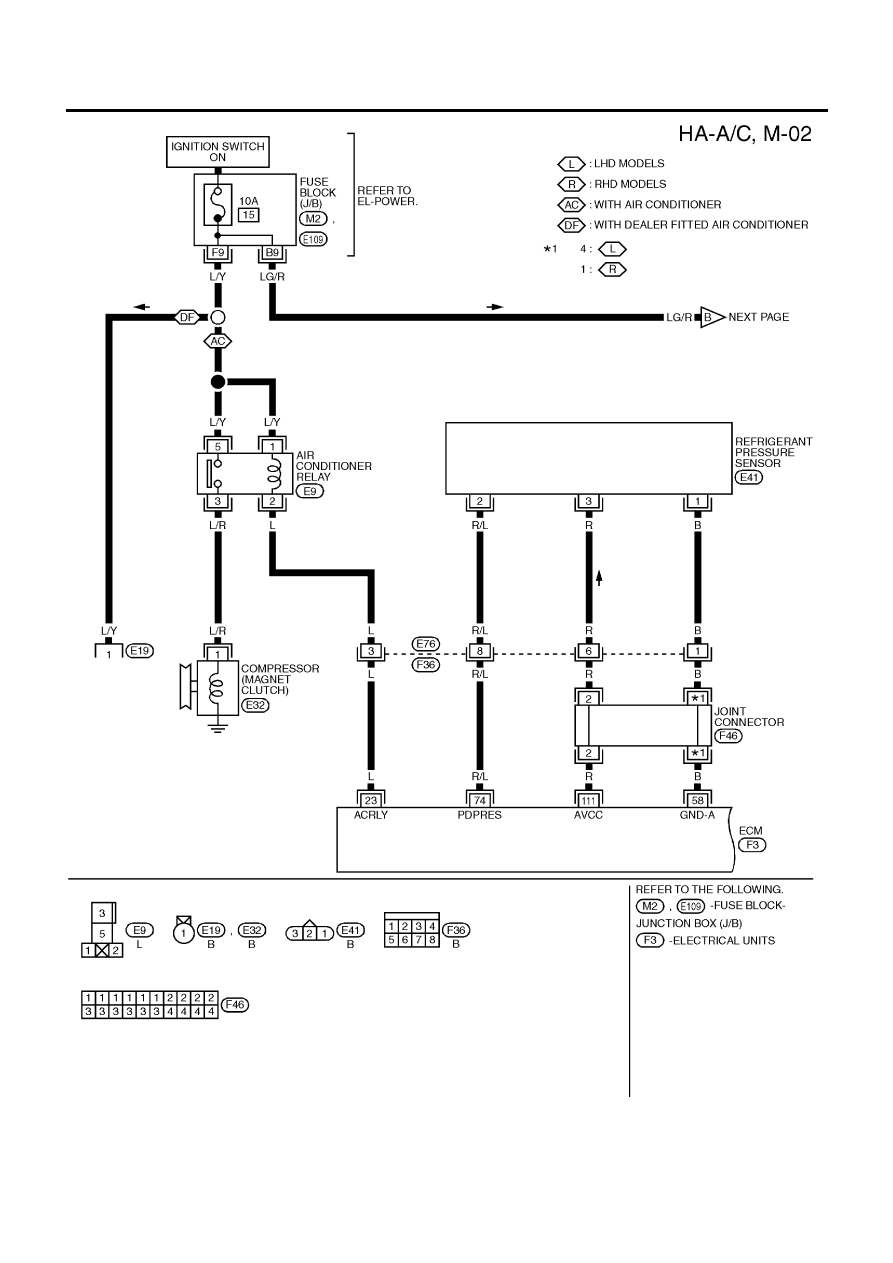
YHA350

TROUBLE DIAGNOSES

Wiring Diagram — A/C, M — (Cont’d)

HA-35

YHA351

TROUBLE DIAGNOSES

Wiring Diagram — A/C, M — (Cont’d)

HA-36

Models with Diesel Engine

NLHA0128S0402

YHA352

TROUBLE DIAGNOSES

Wiring Diagram — A/C, M — (Cont’d)

HA-37

YHA353

TROUBLE DIAGNOSES

Wiring Diagram — A/C, M — (Cont’d)

HA-38

YHA354

TROUBLE DIAGNOSES

Wiring Diagram — A/C, M — (Cont’d)

HA-39

How to Perform Trouble Diagnoses for Quick
and Accurate Repair

NLHA0129

WORK FLOW

NLHA0129S01

SHA900E

*1: HA-41

SYMPTOM TABLE

NLHA0129S02

Symptom

Reference page

+

Intake door does not change.

+

Go to Trouble Diagnosis Procedure for Intake Door.

HA-43

+

Air outlet does not change.

+

Go to Trouble Diagnosis Procedure for mode door.

HA-47

+

Air mix door does not change.

+

Go to Trouble Diagnosis Procedure for Air mix door.

HA-49

+

Max hot door does not change.

+

Go to Trouble Diagnosis Procedure for Max Hot Door.

HA-51

+

Blower motor does not rotate at all.

+

Go to Trouble Diagnosis Procedure for Blower Motor.

HA-55

+

Magnet clutch does not engage when A/C switch and
fan switch are ON.

+

Go to Trouble Diagnosis Procedure for Magnet Clutch.

HA-62

+

Insufficient cooling.

+

Go to Trouble Diagnosis Procedure for Insufficient cool-
ing.

HA-75

+

Insufficient heating.

+

Go to Trouble Diagnosis Procedure for Insufficient
heating.

HA-83

+

Noise

+

Go to Trouble Diagnosis Procedure for Noise.

HA-84

TROUBLE DIAGNOSES

How to Perform Trouble Diagnoses for Quick and Accurate Repair

HA-40

Operational Check

=NLHA0130

The purpose of the operational check is to confirm that the system
operates properly.

CONDITIONS:

NLHA0130S01

+

Engine running and at normal operating temperature.

NHA374

PROCEDURE:

NLHA0130S02

1. Check Blower

NLHA0130S0201

1.

Turn fan switch to 1-speed.
Blower should operate on 1-speed.

2.

Then turn fan switch to 2-speed, and continue checking blower
speed until all speeds are checked.

3.

Leave blower on 4-speed.

If NG, go to trouble diagnosis procedure for blower motor (HA-55).
If OK, continue with next check.

NHA375

2. Check Discharge Air

NLHA0130S0202

1.

Turn mode control knob to each position.

NHA376

2.

Confirm that discharge air comes out according to the air dis-
tribution table at left.

Refer to “Discharge Air Flow”, HA-19.
If NG, go to trouble diagnosis procedure for mode door motor
(HA-47).
If OK, continue with next check.

TROUBLE DIAGNOSES

Operational Check

HA-41

NHA377

3. Check Recirculation

NLHA0130S0203

1)

Press the Recirculation (REC) switch. Recirculation indicator
should illuminate.

2)

Listen for intake door position change.

If NG, go to trouble diagnosis procedure for intake door (HA-43).
If OK, continue with next check.

NHA378

4. Check Temperature Decrease

NLHA0130S0204

1.

Turn the temperature control knob to full cold.

2.

Check for cold air at discharge air outlets.

If NG, go to trouble diagnosis procedure for insufficient cooling
(HA-75).
If OK, continue with next check.

NHA379

5. Check Temperature Increase

NLHA0130S0205

1.

Turn the temperature control knob to full hot.

2.

Check for hot air at discharge air outlets.

If NG, go to trouble diagnosis procedure for insufficient heating
(HA-83).

NHA380

6. Check Air Conditioner Switch

NLHA0130S0206

Turn the fan control switch to the desired (1 to 4 speed) position
and push the A/C switch to turn ON the air conditioner.
The indicator lamp should come on when air conditioner is ON.
If NG, go to trouble diagnosis procedure for magnet clutch (HA-62).

TROUBLE DIAGNOSES

Operational Check (Cont’d)

HA-42

Intake Door

TROUBLE DIAGNOSIS PROCEDURE FOR INTAKE DOOR

=NLHA0133

SYMPTOM:

+

Intake door does not change.

INSPECTION FLOW

NHA381

*1: HA-41

*2: HA-40

*3: HA-40

TROUBLE DIAGNOSES

Intake Door

HA-43

NHA463

COMPONENT DESCRIPTION

NLHA0209

Intake Door Motor

NLHA0209S01

The intake door motor is attached to the intake unit. It rotates so
that air is drawn from inlets set by the heater control panel. Motor
rotation is conveyed to a lever which activates the intake door.

DIAGNOSTIC PROCEDURE FOR INTAKE DOOR
MOTOR CIRCUIT

NLHA0210

1

CHECK POWER SUPPLY FOR HEATER CONTROL PANEL

Do approx. 12 volts exist between heater control panel harness terminal No. 1 and body ground?

NHA462

Yes or No

Yes

©

GO TO 2.

No

©

Check 10A (No. 15) fuse at fuse block. Refer to EL-10, “Wiring Diagram — POWER —”.

2

CHECK RECIRCULATION (REC) SWITCH

Refer to HA-46.

OK or NG

OK

©

GO TO 3.

NG

©

Replace recirculation (REC) switch.

TROUBLE DIAGNOSES

Intake Door (Cont’d)

HA-44

3

CHECK GROUND CIRCUIT FOR RECIRCULATION (REC) SWITCH

Check circuit continuity between heater control panel harness terminal No. 5 and body ground.

NHA464

Continuity should exist.

If OK, check harness for short.

OK or NG

OK

©

GO TO 4.

Ng

©

Repair harness or connector.

4

CHECK POWER SUPPLY FOR INTAKE DOOR MOTOR

Do approx. 12 volts exist between intake door motor harness terminal No. 1, 2 and body ground?

NHA401

Yes or No

Yes

©

Replace intake door motor.

No

©

GO TO 5.

TROUBLE DIAGNOSES

Intake Door (Cont’d)

HA-45

5

CHECK CIRCUIT CONTINUITY BETWEEN HEATER CONTROL PANEL AND INTAKE DOOR MOTOR

Check circuit continuity between heater control panel harness terminal No. 10 (11) and intake door motor harness terminal
No. 2 (1)

NHA465

Continuity should exist.

If OK, check harness for short.

OK or NG

OK

©

Replace heater control panel.

NG

©

Repair harness or connector.

NHA466

ELECTRICAL COMPONENT INSPECTION

NLHA0216

Recirculation (REC) Switch

NLHA0216S01

Check continuity between terminals.

Terminals

REC switch

Continuity

1 - 5

ON

Yes

OFF

No

NHA405

Intake Door Motor

NLHA0216S02

Supply 12V direct current to intake door motor terminal No. 1 and
2.

12V direct current supply terminals

Intake door position

+

1

2

FRE

2

1

REC

TROUBLE DIAGNOSES

Intake Door (Cont’d)

HA-46

Mode Door

TROUBLE DIAGNOSIS PROCEDURE FOR MODE DOOR

=NLHA0137

SYMPTOM:

+

Air outlet does not change.

INSPECTION FLOW

NHA382

*1: HA-19
*2: HA-41

*3: HA-48

*4: HA-40

TROUBLE DIAGNOSES

Mode Door

HA-47

RHA695H

RHA745H

CONTROL LINKAGE ADJUSTMENT

NLHA0139

Mode Door

NLHA0139S01

1.

Turn the mode control knob to VENT position.

2.

Move side link by hand and hold mode door in VENT position.

3.

Pull on the cable cover in the direction of the arrow, then clamp
it.

After positioning control cable, check that it operates
properly.

TROUBLE DIAGNOSES

Mode Door (Cont’d)

HA-48

Air Mix Door

TROUBLE DIAGNOSIS PROCEDURE FOR AIR MIX DOOR

=NLHA0140

SYMPTOM:

+

Air mix door does not change.

INSPECTION FLOW

NHA383

*1: HA-50
*2: HA-41

*3: HA-41

*4: HA-40

TROUBLE DIAGNOSES

Air Mix Door

HA-49


Content      ..     163      164      165      166     ..