Nissan Almera Tino V10 (2001 year). Manual - part 166
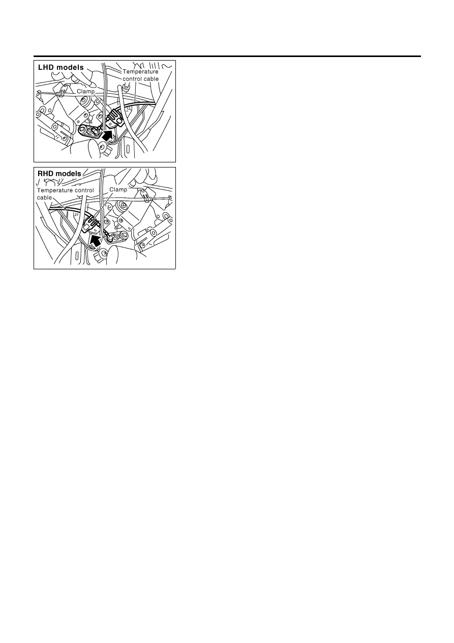
RHA697H
RHA746H
CONTROL LINKAGE ADJUSTMENT
NLHA0143
Air Mix Door
NLHA0143S01
1.
Turn the temperature control knob to full hot position.
2.
Move air mix door lever by hand and hold it at the full hot
position.
3.
Pull on the cable cover in the direction of the arrow, then clamp
it.
After positioning control cable, check that it operates
properly.
TROUBLE DIAGNOSES
Air Mix Door (Cont’d)
HA-50