Index Manuals Nissan Almera Tino V10 (2001 year) - Service and Repair Manual
Search copyright infringement
Content .. 114 115 116 117 ..
Nissan Almera Tino V10 (2001 year). Manual - part 116
YEL889B
ILLUMINATION
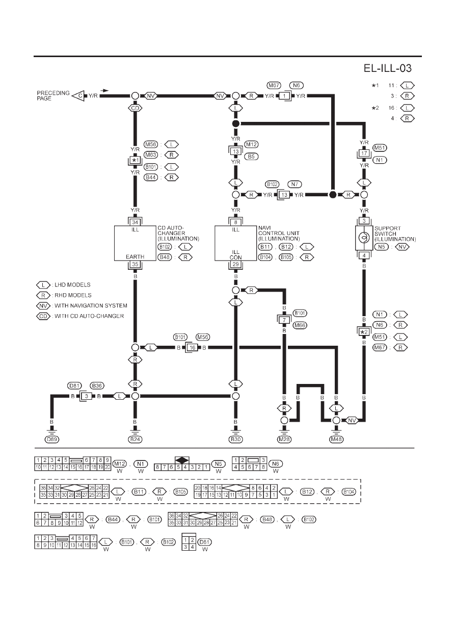
Wiring Diagram — ILL — (Cont’d)
EL-111