Nissan Almera Tino V10 (2001 year). Manual - part 117


  Index      Manuals     Nissan Almera Tino V10 (2001 year) - Service and Repair Manual


Search            copyright infringement  


Content      ..     115      116      117      118     ..


Nissan Almera Tino V10 (2001 year). Manual - part 117


2

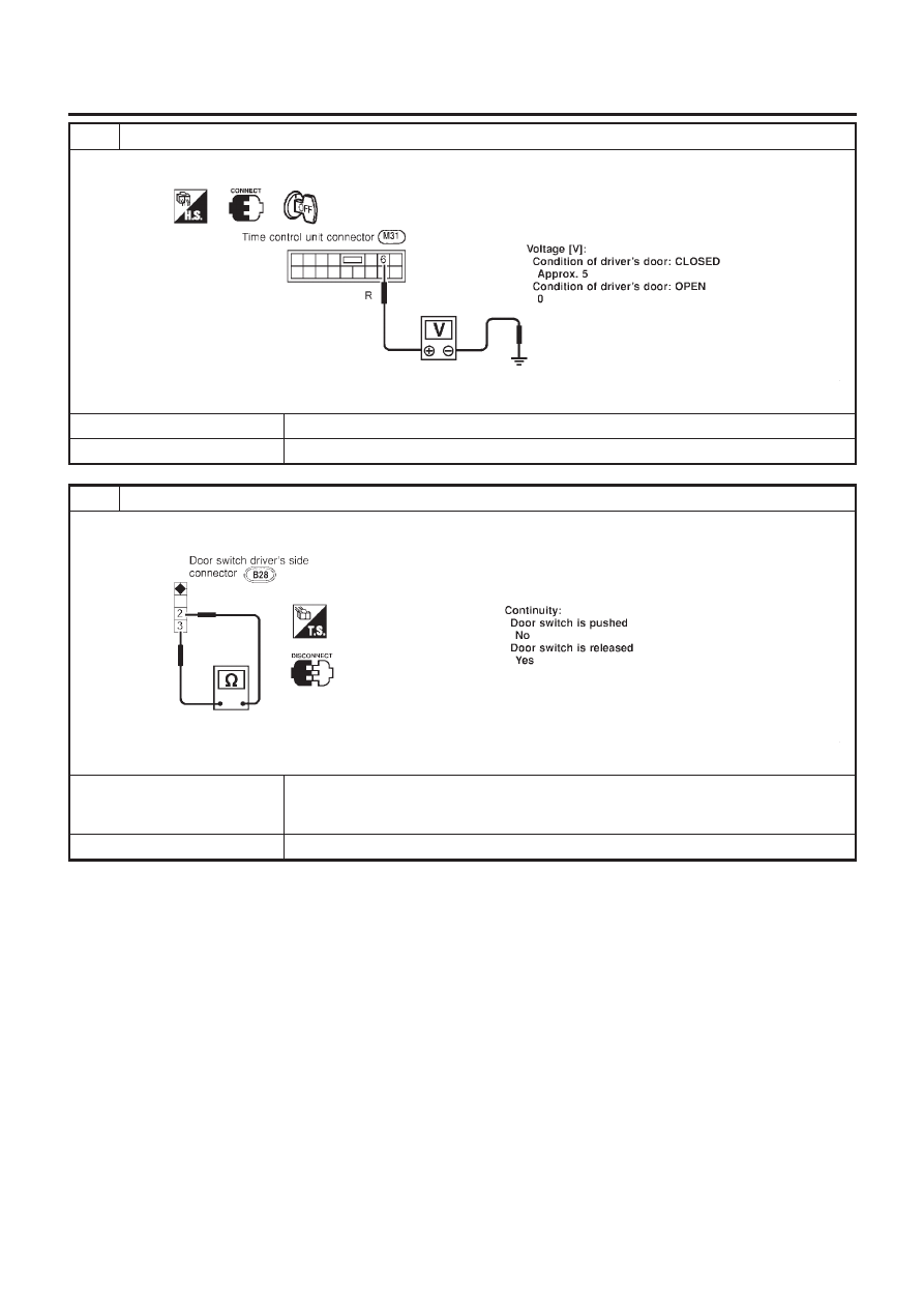
CHECK DOOR SWITCH INPUT SIGNAL

Check voltage between time control unit harness connector terminal 6 and ground.

NEL647

OK or NG

OK

©

GO TO 4.

NG

©

GO TO 3.

3

CHECK DRIVER SIDE DOOR SWITCH

Check continuity between terminals 2 and 3.

NEL648

OK or NG

OK

©

Check the following.

+

Driver side door switch ground circuit and condition

+

Harness for open or short between time control unit and driver side door switch

NG

©

Replace driver side door switch.

INTERIOR ROOM LAMP

Trouble Diagnoses (Cont’d)

EL-127

4

CHECK FRONT DOOR UNLOCK SENSOR INPUT SIGNAL

Check voltage between time control unit harness connector terminal 35 and ground.

NEL649

OK or NG

OK

©

Replace time control unit.

NG

©

GO TO 5.

5

CHECK FRONT DOOR UNLOCK SENSOR

1. Disconnect front door unlock sensor harness connector.
2. Check continuity between door unlock sensor terminals.

NEL650

OK or NG

OK

©

Check the following.

+

Door unlock sensor ground circuit

+

Harness for open or short between time control unit and door unlock sensor

NG

©

Replace door unlock sensor.

INTERIOR ROOM LAMP

Trouble Diagnoses (Cont’d)

EL-128

Wiring Diagram — INT/L —

NLEL0532

WHERE FITTED

NLEL0532S01

YEL418C

VANITY MIRROR AND LUGGAGE ROOM LAMPS

Wiring Diagram — INT/L —

EL-129

Component Parts and Harness Connector
Location

NLEL0441

NEL781

System Description

NLEL0442

UNIFIED CONTROL METER

NLEL0442S01

+

Speedometer, odo/trip meter, tachometer, fuel gauge and water temperature gauge are controlled totally
by control unit built-in combination meter.

+

Digital meter is adopted for odo/trip meter.*
*The record of the odo meter is kept even if the battery cable is disconnected. The record of the trip meter
is erased when the battery cable is disconnected.

+

Odo/trip meter segment can be checked in diagnosis mode.

+

Meter/gauge can be checked in diagnosis mode.

HOW TO CHANGE THE DISPLAY FOR ODO/TRIP METER

NLEL0442S02

SEL394X

NOTE:
Turn ignition switch to the “ON” position to operate odo/trip meter.

METERS AND GAUGES

Component Parts and Harness Connector Location

EL-130

POWER SUPPLY AND GROUND CIRCUIT

NLEL0442S03

Power is supplied at all times

+

through 10A fuse [No. 12, located in the fuse block (J/B)]

+

to combination meter terminal 8.

With the ignition switch in the ON or START position, power is supplied

+

through 10A fuse [No. 30, located in the fuse block (J/B)]

+

to combination meter terminal 9.

Ground is supplied

+

through body grounds M28 and M48

+

to combination meter terminal 7.

WATER TEMPERATURE GAUGE

NLEL0442S04

The water temperature gauge indicates the engine coolant temperature. The reading on the gauge is based
on the resistance of the thermal transmitter.
As the temperature of the coolant increases, the resistance of the thermal transmitter decreases. A variable
ground is supplied to terminal 5 of the combination meter for the water temperature gauge. The needle on the
gauge moves from “C” to “H”.

TACHOMETER

NLEL0442S05

The tachometer indicates engine speed in revolutions per minute (rpm).
The tachometer is regulated by a signal

+

from terminal 32 (Gasoline engine models) or 439 (Diesel engine models) of the ECM

+

to combination meter terminal 19 for the tachometer.

FUEL GAUGE

NLEL0442S06

The fuel gauge indicates the approximate fuel level in the fuel tank.
The fuel gauge is regulated by a variable ground signal supplied

+

from body grounds M28 and M48

+

through terminals 4 and 7 of combination meter,

+

through terminal 1 of the fuel level sensor unit and

+

through terminal 4 of the fuel level sensor unit

+

to combination meter terminal 3 for the fuel gauge.

SPEEDOMETER

NLEL0442S07

The combination meter provides a voltage signal to the vehicle speed sensor for the speedometer.
The voltage is supplied

+

from combination meter terminal 18 for the speedometer

+

to terminal 1 of the vehicle speed sensor.

Ground is supplied

+

from body grounds M28 and M48

+

through terminals 6 and 7 of combination meter

+

to terminal 2 of the vehicle speed sensor.

The speedometer converts the voltage into the vehicle speed displayed.

METERS AND GAUGES

System Description (Cont’d)

EL-131

Combination Meter

NLEL0443

CHECK

NLEL0443S01

Models with NATS security indicator on dash board

NLEL0443S0105

YEL990B

METERS AND GAUGES

Combination Meter

EL-132

Models with NATS security indicator in combination meter

NLEL0443S0106

YEL488C

METERS AND GAUGES

Combination Meter (Cont’d)

EL-133

Schematic

NLEL0444

MODELS WITH NATS SECURITY INDICATOR ON DASH
BOARD

NLEL0444S02

YEL991B

METERS AND GAUGES

Schematic

EL-134

MODELS WITH NATS SECURITY INDICATOR IN
COMBINATION METER

NLEL0444S03

YEL489C

METERS AND GAUGES

Schematic (Cont’d)

EL-135

Construction

NLEL0445

NEL739

METERS AND GAUGES

Construction

EL-136

Wiring Diagram — METER —

NLEL0446

MODELS WITH FUSE AND FUSIBLE LINK BOX E43

NLEL0446S01

YEL894B

METERS AND GAUGES

Wiring Diagram — METER —

EL-137

YEL895B

METERS AND GAUGES

Wiring Diagram — METER — (Cont’d)

EL-138

MODELS WITH FUSE AND FUSIBLE LINK BOX E90

NLEL0446S02

YEL419C

METERS AND GAUGES

Wiring Diagram — METER — (Cont’d)

EL-139

YEL420C

METERS AND GAUGES

Wiring Diagram — METER — (Cont’d)

EL-140

Combination Meter Self-Diagnosis

NLEL0447

PERFORMING SELF-DIAGNOSIS MODE

NLEL0447S01

1.

Turn the ignition switch to the “LOCK” position.

2.

Press both reset buttons on the combination meter and keep
them depressed.

3.

Turn the ignition switch to the “ON” position, while keeping the
reset buttons pressed.

4.

Release both reset buttons then self-diagnosis will start. The
sequence (A to L) is activated by press the either reset buttons.

NOTE:
If either reset button is not pressed for 20 seconds at each step or
if the ignition switch is turned OFF, the self-diagnosis mode is
exited.

Check items

Display

Remarks

A)

Odometer segment test

SEL434X

All odo trip meter segments are ON.

B)

Work instruction code

SEL435X

This information is not used for service. Please skip this
step.

C)

Software code

NEL735

This information is not used for service. Please skip this
step.

D)

EEPROM code

NEL736

This information is not used for service. Please skip this
step.

E)

Hardware code

NEL737

This information is not used for service. Please skip this
step.

F)

PCB code

NEL738

This information is not used for service. Please skip this
step.

G)

Meter/gauge test
(Sweeping movement)

SEL440X

Tachometer, speedometer, fuel level gauge and water
temperature gauge have sweeping movement test.
(The meter/gauges operate MIN.

MAX., MAX.

MIN.

for 2 times)
The odo trip meter segment flashes during the sweep
movement.

METERS AND GAUGES

Combination Meter Self-Diagnosis

EL-141

Check items

Display

Remarks

H)

Error 1
(Bit 0 - Bit 3)

SEL441X

The segment of each bit displays “0”, meaning no failure.
If the bit(s) displays figures other than “0”, the item of the
bit has failed.
For details, refer to “Failure chart for Error 1 and Error E”
below.

I)

Error E
(Bit 4 - Bit 7)

SEL442X

J)

Fuel warning lamp test

SEL443X

Fuel warning lamp is on and odo trip meter segment
“FUEL” flashes.

K)

Fuel gauge calibration
(CAL)

SEL444X

This information is not used for service. Please skip this
step.

L)

Fuel gauge calibration
(OLD)

SEL445X

This information is not used for service. Please skip this
step.

Failure Chart for “Error 1” and “Error E”

NLEL0447S0101

Bit

Detectable items

Description of the failure

Displayed figure on the

bit

Failure

No failure

0

Speedometer input sig-
nal

No input signal
When no signal is detected for 30 minutes continuously with
the ignition ON, it should be judged as signal failure.
(If input signal is detected later, then the judgement will be
canceled immediately.)

1

0

Abnormal input signal
When any signal of frequency which would not exist in normal
conditions is detected, it should be judged as signal failure.

2

1

Tachometer input signal

No input signal
When no signal is detected for 30 minutes continuously with
the ignition ON, it should be judged as signal failure.
(If input signal is detected later, then the judgement will be
canceled immediately.)

1

0

Abnormal input signal
When any signal of frequency which would not exist in normal
conditions is detected, it should be judged as signal failure.

2

METERS AND GAUGES

Combination Meter Self-Diagnosis (Cont’d)

EL-142


Content      ..     115      116      117      118     ..