Nissan Almera Tino V10 (2001 year). Manual - part 85
 

  Index      Manuals     Nissan Almera Tino V10 (2001 year) - Service and Repair Manual


Search            copyright infringement  


Content      ..     83      84      85      86     ..


Nissan Almera Tino V10 (2001 year). Manual - part 85


Description

NLEC1633

SYSTEM DESCRIPTION

NLEC1633S01

Sensor

Input Signal to ECM

ECM func-

tion

Actuator

Camshaft position sensor

Engine speed

EGR vol-
ume control

EGR volume control valve

Mass air flow sensor

Amount of intake air

Engine coolant temperature sensor

Engine coolant temperature

Ignition switch

Start signal

Throttle position sensor

Throttle position

Vehicle speed sensor

Vehicle speed

Battery

Battery voltage

Air conditioner switch

Air conditioner operation

Power steering oil pressure switch

Power steering load signal

Electrical load

Electrical load signal

Park/Neutral position switch

Park/Neutral position

TCM (Transmission Control Module)

Gear position, shifting signal

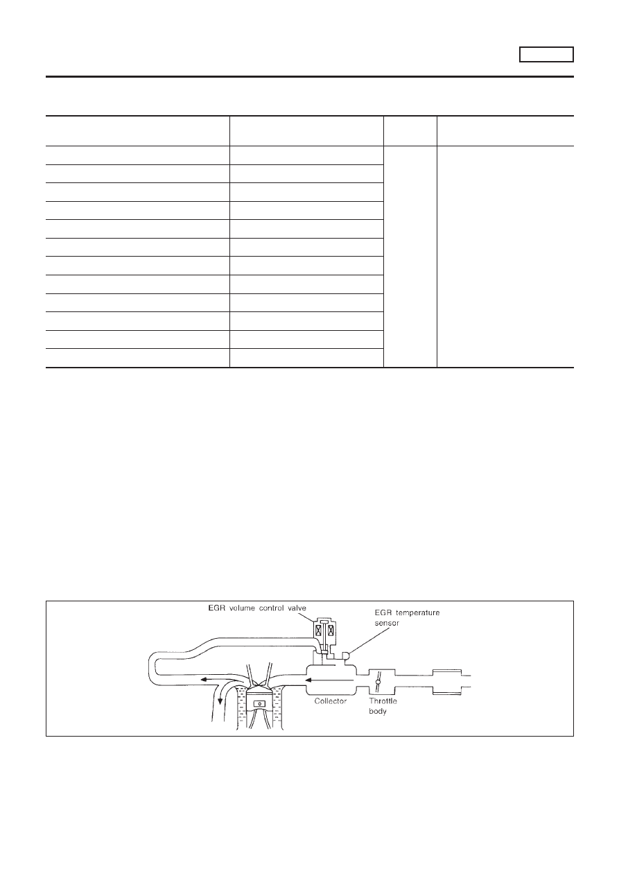
This system controls flow rate of EGR led from exhaust manifold
to intake manifold. The opening of the EGR by-pass passage in the
EGR volume control valve changes to control the flow rate. A
built-in step motor moves the valve in steps corresponding to the
ECM output pulses. The opening of the valve varies for optimum
engine control. The optimum value stored in the ECM is determined
by considering various engine conditions. The EGR volume control
valve remains close under the following conditions.

+

Extremely light load engine operation

+

Mass air flow sensor malfunction

+

Engine idling

+

Low engine coolant temperature

+

Excessively high engine coolant temperature

+

High-speed engine operation

+

Wide open throttle

+

Low battery voltage

+

Engine starting

SEF551W

DTC P1402 EGR FUNCTION (OPEN) (WHERE FITTED)

SR20DE

Description

EC-921

SEF552W

COMPONENT DESCRIPTION

NLEC1633S02

EGR Volume Control Valve

NLEC1633S0201

The EGR volume control valve uses a step motor to control the flow
rate of EGR from exhaust manifold. This motor has four winding
phases. It operates according to the output pulse signal of the
ECM. Two windings are turned ON and OFF in sequence. Each
time an ON pulse is issued, the valve opens or closes, changing
the flow rate. When no change in the flow rate is needed, the ECM
does not issue the pulse signal. A certain voltage signal is issued
so that the valve remains at that particular opening.

CONSULT-II Reference Value in Data Monitor
Mode

NLEC1634

Specification data are reference values.

MONITOR ITEM

CONDITION

SPECIFICATION

EGR TEMP SEN

+

Engine: After warming up

Less than 4.5V

EGR VOL CON/V

+

Engine: After warming up

+

Air conditioner switch: “OFF”

+

Shift lever: “N”

+

No-load

Idle

0 step

Revving engine up to 3,000 rpm
quickly

10 - 55 step

ECM Terminals and Reference Value

NLEC1635

Specification data are reference values, and are measured between each terminal and ground.

CAUTION:

Do not use ECM ground terminals when measuring input/output voltage. Doing so may result in dam-
age to the ECM’s transistor. Use a ground other than ECM terminals, such as the ground.

TERMI-

NAL NO.

WIRE

COLOR

ITEM

CONDITION

DATA (DC Voltage)

8
9

17
18

SB
W/B
R/W
G/R

EGR volume control valve

[Engine is running.]

+

Warm-up condition

+

Idle speed

0 - 14V

58

B

Sensor’s ground

[Engine is running.]

+

Warm-up condition

+

Idle speed

0V

72

PU

EGR temperature sensor

[Engine is running.]

+

Warm-up condition

+

Idle speed

Less than 4.5V

[Engine is running.]

+

Warm-up condition

+

EGR system is operating.

0 - 1.0V

SEF073P

On Board Diagnosis Logic

NLEC1636

If EGR temperature sensor detects EGR flow under the condition
that does not call for EGR, a high-flow malfunction is diagnosed.
NOTE:
Diagnosis for this DTC will occur when engine coolant temperature
is below 50 to 60°C (122 to 140°F). Therefore, it will be better to
turn ignition switch “ON” (start engine) at the engine coolant tem-
perature below 30°C (86°F) when starting DTC confirmation pro-
cedure.

DTC P1402 EGR FUNCTION (OPEN) (WHERE FITTED)

SR20DE

Description (Cont’d)

EC-922

DTC No.

Malfunction is detected when ...

Check Items (Possible Cause)

P1402

+

EGR flow is detected under conditions that do not call for
EGR.

+

Harness or connectors
(The valve circuit is open or shorted.)

+

EGR volume control valve leaking or stuck open

+

EGR temperature sensor

SEF202Y

SEF851Y

SEF852Y

SEF236Y

DTC Confirmation Procedure

NLEC1637

NOTE:
If “DTC Confirmation Procedure” has been previously conducted,
always turn ignition switch “OFF” and wait at least 10 seconds
before conducting the next test.
TESTING CONDITION:

+

Always perform at a temperature above −10°C (14°F).

+

Engine coolant temperature and EGR temperature must
be verified in “DATA MONITOR” mode with CONSULT-II
before starting DTC WORK SUPPORT test. If it is out of
range below, the test cannot be conducted.
COOLAN TEMP/S: −10 to 50°C (14 to 122°F)*
EGR TEMP SEN: Less than 4.8V
If the values are out of the ranges indicated above, park
the vehicle in a cool place and allow the engine tempera-
ture to stabilize. Do not attempt to reduce the engine cool-
ant or EGR temperature with a fan or means other than
ambient air. Doing so may produce an inaccurate diagnos-
tic result.

*: Although CONSULT-II screen displays “−10 to 40°C (14 to
104°F)” as a range of engine coolant temperature, ignore it.

With CONSULT-II

1)

Turn ignition switch “OFF” and wait at least 10 seconds, then
turn ignition switch “ON”.

2)

Select “EGR SYSTEM P1402” of “EGR SYSTEM” in “DTC
WORK SUPPORT” mode with CONSULT-II.

3)

Touch “START”. Follow instruction of CONSULT-II.

4)

Start engine and let it idle until “TESTING” on CONSULT-II
screen is turned to “COMPLETED”. (It will take 60 seconds or
more.)
If “TESTING” is not displayed after 5 minutes, turn ignition
“OFF” and cool the engine coolant temperature to the
range of −10 to 50°C (14 to 122°F). Retry from step 1.

5)

Make sure that “OK” is displayed after touching “SELF-DIAG
RESULTS”.

If

“NG”

is

displayed,

refer

to

“Diagnostic

Procedure”, EC-926.

DTC P1402 EGR FUNCTION (OPEN) (WHERE FITTED)

SR20DE

On Board Diagnosis Logic (Cont’d)

EC-923

SEF947X

With GST

1)

Turn ignition switch “ON” and select “MODE 1” with GST.

2)

Check that engine coolant temperature is within the range of
−10 to 50°C (14 to 122°F).

3)

Check that voltage between ECM terminal 72 (EGR tempera-
ture sensor signal) and ground is less than 4.8V.

4)

Start engine and let it idle for at least 60 seconds.

5)

Stop engine.

6)

Perform from step 1 to 4.

7)

Select “MODE 3” with GST.

8)

If DTC is detected, go to “Diagnostic Procedure”, EC-926.

+

When using GST, “DTC Confirmation Procedure” should
be performed twice as much as when using CONSULT-II
because GST cannot display MODE 7 (1st trip DTC) con-
cerning this diagnosis. Therefore, using CONSULT-II is
recommended.

DTC P1402 EGR FUNCTION (OPEN) (WHERE FITTED)

SR20DE

DTC Confirmation Procedure (Cont’d)

EC-924

Wiring Diagram

NLEC1638

YEC700

DTC P1402 EGR FUNCTION (OPEN) (WHERE FITTED)

SR20DE

Wiring Diagram

EC-925

Diagnostic Procedure

NLEC1639

1

CHECK POWER SUPPLY

1. Disconnect EGR volume control valve harness connector.

SEF216X

2. Turn ignition switch “ON”.
3. Check voltage between EGR volume control valve terminals 2, 5 and ground with CONSULT-II or tester.

SEF782Z

OK or NG

OK

©

GO TO 3.

NG

©

GO TO 2.

2

DETECT MALFUNCTIONING PART

Check the following.

+

15A fuse

+

Harness connectors E76, F36

+

ECM relay

+

Harness for open or short between EGR volume control valve and fuse.

©

Repair harness or connectors.

3

CHECK OUTPUT SIGNAL CIRCUIT

1. Turn ignition switch “OFF”.
2. Disconnect ECM harness connector.
3. Check harness continuity between

ECM terminal 8 and EGR volume control valve terminal 1,
ECM terminal 9 and EGR volume control valve terminal 4,
ECM terminal 17 and EGR volume control valve terminal 3,
ECM terminal 18 and EGR volume control valve terminal 6.
Refer to wiring diagram.

Continuity should exist.

4. Also check harness for short to ground and short to power.

OK or NG

OK

©

GO TO 4.

NG

©

Repair open circuit, short to ground or short to power in harness connectors.

DTC P1402 EGR FUNCTION (OPEN) (WHERE FITTED)

SR20DE

Diagnostic Procedure

EC-926

4

CHECK EGR TEMPERATURE SENSOR

Refer to “COMPONENT INSPECTION”, EC-920.

OK or NG

OK

©

GO TO 5.

NG

©

Replace EGR temperature sensor.

5

CHECK EGR VOLUME CONTROL VALVE

Refer to “COMPONENT INSPECTION”, EC-847.

OK or NG

OK

©

GO TO 6.

NG

©

Replace EGR volume control valve.

6

CHECK INTERMITTENT INCIDENT

Perform “TROUBLE DIAGNOSIS FOR INTERMITTENT INCIDENT”, EC-670.

©

INSPECTION END

DTC P1402 EGR FUNCTION (OPEN) (WHERE FITTED)

SR20DE

Diagnostic Procedure (Cont’d)

EC-927

System Description

NLEC1641

The malfunction information related to CVT is transferred through the line (circuit) from TCM (Transmission
Control Module) to ECM. Therefore, be sure to erase the malfunction information such as DTC not only in TCM
(Transmission Control Module) but also ECM after the CVT related repair.

ECM Terminals and Reference Value

NLEC1642

Specification data are reference values and are measured between each terminal and ground.

CAUTION:

Do not use ECM ground terminals when measuring input/output voltage. Doing so may result in dam-
age to the ECM’s transistor. Use a ground other than ECM terminals, such as the ground.

TERMI-

NAL

NO.

WIRE

COLOR

ITEM

CONDITION

DATA (DC Voltage)

91

PU

CVT check signal

[Ignition switch “ON”]

0 - Approximately 5V

On Board Diagnosis Logic

NLEC1643

DTC No.

Malfunction is detected when ...

Check Items (Possible Cause)

P1605

+

An incorrect signal from TCM (Transmission Control
Module) is sent to ECM.

+

Harness or connectors
[The communication line circuit between ECM
and TCM (Transmission Control Module) is open
or shorted.]

+

Dead (Weak) battery

+

TCM (Transmission Control Module)

SEF058Y

DTC Confirmation Procedure

NLEC1644

NOTE:
If “DTC CONFIRMATION PROCEDURE” has been previously
conducted, always turn ignition switch “OFF” and wait at least 10
seconds before conducting the next test.

With CONSULT-II

1)

Turn ignition switch “ON”.

2)

Select “DATA MONITOR” mode with CONSULT-II.

3)

Start engine and let it idle for at least 40 seconds.

4)

If 1st trip DTC is detected, go to “Diagnostic Procedure”,
EC-930.

With GST

Follow the procedure “With CONSULT-II” above.

DTC P1605 A/T DIAGNOSIS COMMUNICATION LINE

SR20DE

System Description

EC-928

Wiring Diagram

NLEC1645

YEC709

DTC P1605 A/T DIAGNOSIS COMMUNICATION LINE

SR20DE

Wiring Diagram

EC-929

Diagnostic Procedure

NLEC1646

1

CHECK INPUT SIGNAL CIRCUIT

1. Turn ignition switch “OFF”.
2. Disconnect ECM harness connector and TCM harness connector.

SEF116Y

3. Check harness continuity between ECM terminal 91 and TCM terminal 15.

Refer to Wiring Diagram.

Continuity should exist.

4. Also check harness for short to ground and short to power.

OK or NG

OK

©

GO TO 2.

NG

©

Repair open circuit or short to ground or short to power in harness or connectors.

2

CHECK INTERMITTENT INCIDENT

Perform “TROUBLE DIAGNOSIS FOR INTERMITTENT INCIDENT”, EC-670.

©

INSPECTION END

DTC P1605 A/T DIAGNOSIS COMMUNICATION LINE

SR20DE

Diagnostic Procedure

EC-930

SEF781Z

Component Description

NLEC1647

When the gear position is “P” or “N”, park/neutral position (PNP)
switch is “ON”.
ECM detects the park/neutral position when continuity with ground
exists.

CONSULT-II Reference Value in Data Monitor
Mode

NLEC1648

Specification data are reference values.

MONITOR ITEM

CONDITION

SPECIFICATION

P/N POSI SW

+

Ignition switch: ON

Shift lever: “P” or “N”

ON

Except above

OFF

ECM Terminals and Reference Value

NLEC1649

Specification data are reference values and are measured between each terminal and ground.

CAUTION:

Do not use ECM ground terminals when measuring input/output voltage. Doing so may result in dam-
age to the ECM’s transistor. Use a ground other than ECM terminals, such as the ground.

TERMI-

NAL

NO.

WIRE

COLOR

ITEM

CONDITION

DATA (DC Voltage)

42

G/OR

PNP switch

[Ignition switch “ON”]

+

Gear position is “N” or “P”

Approximately 0V

[Ignition switch “ON”]

+

Except the above gear position

BATTERY VOLTAGE
(11 - 14V)

On Board Diagnosis Logic

NLEC1650

DTC No.

Malfunction is detected when ...

Check Items (Possible Cause)

P1706

+

The signal of the PNP switch is not changed in the pro-
cess of engine starting and driving.

+

Harness or connectors
(The PNP switch circuit is open or shorted.)

+

PNP switch

DTC Confirmation Procedure

NLEC1651

CAUTION:

Always drive vehicle at a safe speed.
NOTE:
If “DTC Confirmation Procedure” has been previously conducted,
always turn ignition switch “OFF” and wait at least 10 seconds
before conducting the next test.

With CONSULT-II

1)

Turn ignition switch “ON”.

DTC P1706 PARK/NEUTRAL POSITION (PNP) SWITCH

SR20DE

Component Description

EC-931

SEF213Y

2)

Select “P/N POSI SW” in “DATA MONITOR” mode with CON-
SULT-II. Then check the “P/N POSI SW” signal under the fol-
lowing conditions.

Position (Selector lever)

Known-good signal

“N” and “P” position

ON

Except the above position

OFF

If NG, go to “Diagnostic Procedure”, EC-935.
If OK, go to following step.

3)

Select “DATA MONITOR” mode with CONSULT-II.

4)

Start engine and warm it up to normal operating temperature.

5)

Maintain the following conditions for at least 50 consecutive
seconds.

ENG SPEED

1,250 - 3,350 rpm

COOLAN TEMP/S

More than 70°C (158°F)

B/FUEL SCHDL

3.5 - 14.0 msec

VHCL SPEED SE

64 - 130 km/h (40 - 81 MPH)

Selector lever

Suitable position

6)

If 1st trip DTC is detected, go to “Diagnostic Procedure”,
EC-935.

SEF137X

Overall Function Check

NLEC1652

Use this procedure to check the overall function of the park/neutral
position switch circuit. During this check, a 1st trip DTC might not
be confirmed.

Without CONSULT-II

1)

Turn ignition switch “ON”.

2)

Check voltage between ECM terminal 42 (PNP switch signal)
and body ground under the following conditions.

Condition (Gear position)

Voltage (V) (Known good data)

“P” and “N” position

Approx. 0

Except the above position

BATTERY VOLTAGE

(11 - 14V)

3)

If NG, go to “Diagnostic Procedure”, EC-935.

DTC P1706 PARK/NEUTRAL POSITION (PNP) SWITCH

SR20DE

DTC Confirmation Procedure (Cont’d)

EC-932

Wiring Diagram

NLEC1653

TYPE-1

NLEC1653S01

YEC710

DTC P1706 PARK/NEUTRAL POSITION (PNP) SWITCH

SR20DE

Wiring Diagram

EC-933

TYPE-2

NLEC1653S02

YEC929

DTC P1706 PARK/NEUTRAL POSITION (PNP) SWITCH

SR20DE

Wiring Diagram (Cont’d)

EC-934

Diagnostic Procedure

NLEC1654

1 CHECK GROUND CIRCUIT

1. Turn ignition switch “OFF”.
2. Disconnect PNP switch harness connector.

SEF781Z

3. Check harness continuity between PNP switch terminal 2 and engine ground.

Refer to wiring diagram.

Continuity should exist.

4. Also check harness for short to power.

OK or NG

OK 

© 

GO TO 3.

NG 

© 

GO TO 2.

2 DETECT MALFUNCTIONING PART

Check the harness for open or short between PNP switch and body ground.

© 

Repair open circuit or short to power in harness or connectors.

3 CHECK INPUT SIGNAL CIRCUIT

1. Disconnect ECM harness connector.
2. Check harness continuity between ECM terminal 42 and PNP switch terminal 1.

Refer to wiring diagram.

Continuity should exist.

3. Also check harness for short to ground and short to power.

OK or NG

OK 

© 

GO TO 5.

NG 

© 

GO TO 4.

4 DETECT MALFUNCTIONING PART

Check the harness for open or short between ECM and PNP switch.

© 

Repair open circuit or short to ground or short to power in harness or connectors.

5 CHECK PNP SWITCH

Refer to AT-66, “PARK/NEUTRAL POSITION (PNP) SWITCH”.

OK or NG

OK 

© 

GO TO 6.

NG 

© 

Replace PNP switch.

DTC P1706 PARK/NEUTRAL POSITION (PNP) SWITCH 

SR20DE

Diagnostic Procedure

EC-935

6

CHECK INTERMITTENT INCIDENT

Perform “TROUBLE DIAGNOSIS FOR INTERMITTENT INCIDENT”, EC-670.

©

INSPECTION END

DTC P1706 PARK/NEUTRAL POSITION (PNP) SWITCH

SR20DE

Diagnostic Procedure (Cont’d)

EC-936


Content      ..     83      84      85      86     ..