Nissan Almera Tino V10 (2001 year). Manual - part 84
Diagnostic Procedure
NLEC1915
1
CHECK ENGINE START
Turn ignition switch “OFF”, and restart engine.
Is engine running?
Yes or No
Yes
©
GO TO 7.
No
©
GO TO 2.
2
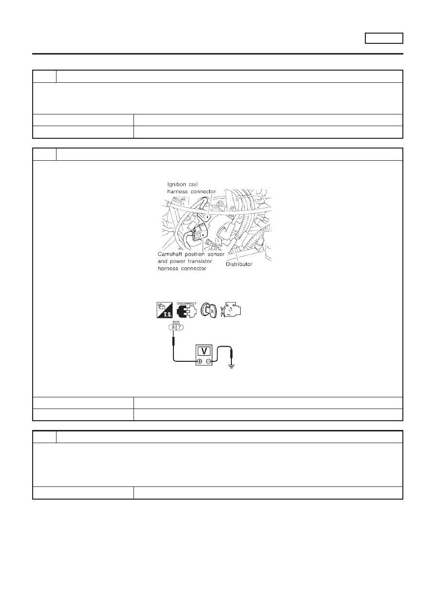
CHECK POWER SUPPLY
1. Turn ignition switch “OFF”.
2. Disconnect ignition coil harness connector.
SEF211X
3. Turn ignition switch “ON”.
4. Check voltage between ignition coil terminal 8 and ground with CONSULT-II or tester.
SEF257W
Voltage: Battery voltage
OK or NG
OK
©
GO TO 4.
NG
©
GO TO 3.
3
DETECT MALFUNCTIONING PART
Check the following.
+
Harness connectors E76, F36
+
ECM relay
+
15A fuse
+
Harness for open or short between ignition coil and fuse
©
Repair harness or connectors.
DTC P1320 IGNITION SIGNAL
SR20DE
Diagnostic Procedure
EC-905