Nissan Almera Tino V10 (2001 year). Manual - part 86
SEF206T
Component Description
NLEC1773
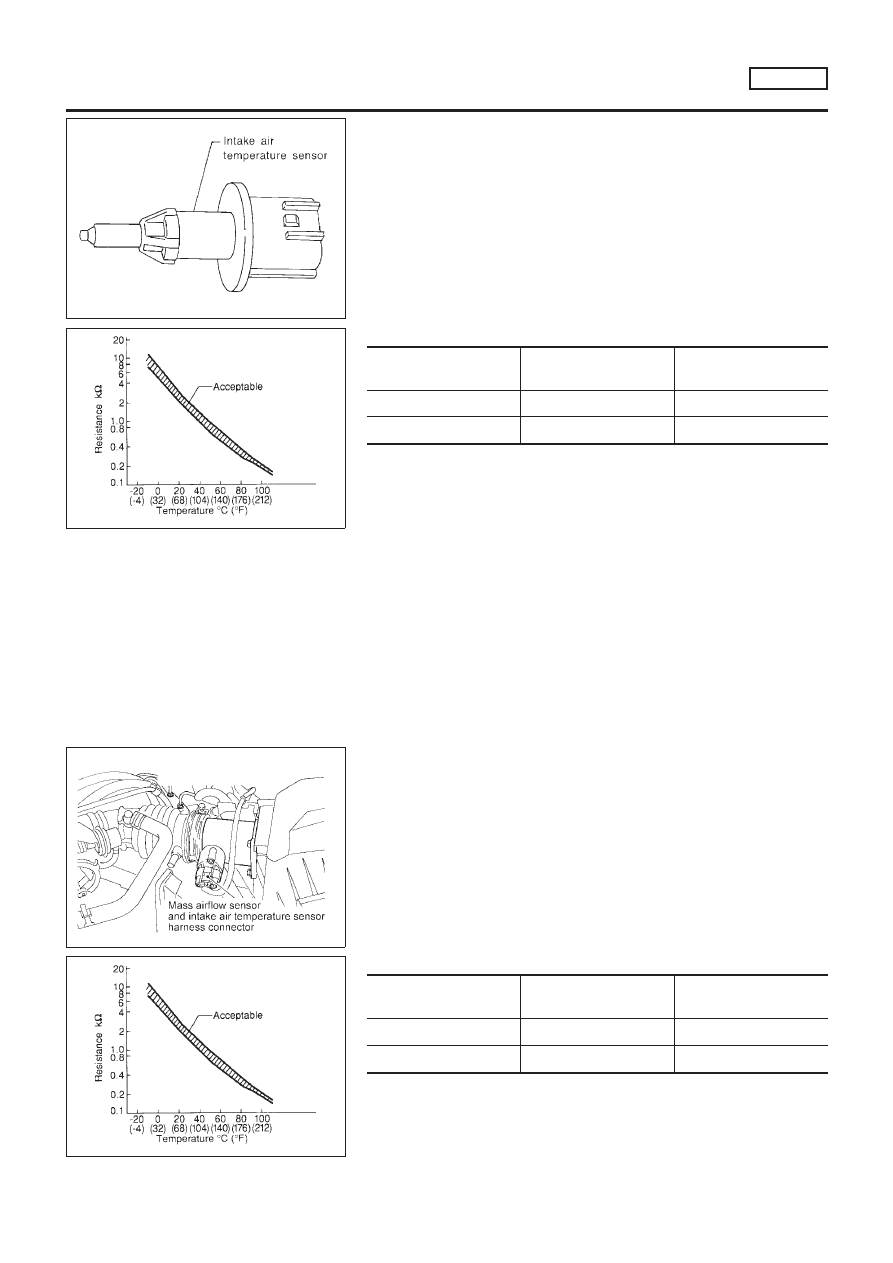
MODELS WITH INTAKE AIR TEMPERATURE SENSOR
ON INTAKE AIR DUCT
NLEC1773S01
The intake air temperature sensor is mounted to the air duct hous-
ing. The sensor detects intake air temperature and transmits a sig-
nal to the ECM.
The temperature sensing unit uses a thermistor which is sensitive
to the change in temperature. Electrical resistance of the thermistor
decreases in response to the temperature rise.
SEF012P
<Reference data>
Intake air temperature
°C (°F)
Voltage*
V
Resistance
k
Ω
20 (68)
3.5
2.1 - 2.9
80 (176)
1.23
0.27 - 0.38
*: These data are reference values and are measured between ECM terminal 64
(Intake air temperature sensor) and ground.
CAUTION:
Do not use ECM ground terminals when measuring input/
output voltage. Doing so may result in damage to the ECM’s
transistor. Use a ground other than ECM terminals, such as
the ground.
NEF306A
MODELS WITH INTAKE AIR TEMPERATURE SENSOR
IN MASS AIR FLOW SENSOR
NLEC1773S02
The intake air temperature sensor is built into the mass air flow
sensor. The sensor detects intake air temperature and transmits a
signal to the ECM.
The temperature sensing unit uses a thermistor which is sensitive
to the change in temperature. Electrical resistance of the thermistor
decreases in response to the temperature rise.
SEF012P
<Reference data>
Intake air temperature
°C (°F)
Voltage*
V
Resistance
k
Ω
20 (68)
3.5
2.1 - 2.9
80 (176)
1.23
0.27 - 0.38
*: These data are reference values and are measured between ECM terminal 64
(Intake air temperature sensor) and ground.
INTAKE AIR TEMPERATURE SENSOR
SR20DE
Component Description
EC-937