Nissan Almera Tino V10 (2001 year). Manual - part 10


  Index      Manuals     Nissan Almera Tino V10 (2001 year) - Service and Repair Manual


Search            copyright infringement  


Content      ..     8      9      10      11     ..


Nissan Almera Tino V10 (2001 year). Manual - part 10


Description

NLAT0232

+

The line pressure sensor detects line pressure of CVT, and
sends TCM the signal.

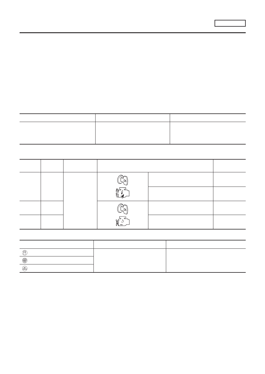
CONSULT-II REFERENCE VALUE IN DATA MONITOR
MODE

NLAT0232S01

Remarks: Specification data are reference values.

Monitor item

Condition

Specification

Line pressure sensor

Throttle valve fully closed (PL Duty: 4%)

Throttle valve fully depressed (PL Duty:

94%)

Approx. 1.0V

Approx. 4.0V

TCM TERMINALS AND REFERENCE VALUE

NLAT0232S02

Remarks: Specification data are reference values.

Terminal

No.

Wire color

Item

Condition

Judgement stan-

dard (Approx.)

37

W

Line pressure
sensor

When engine runs at idle speed.

1.0V

When engine runs at stall speed.

4.0V

42

B

46

R/L

4.5 - 5.5V

ON BOARD DIAGNOSIS LOGIC

NLAT0232S03

Diagnostic trouble code

Malfunction is detected when ...

Check items (Possible cause)

: LINE PRESS SEN

TCM receives an excessively low or high
voltage from the step motor.

+

Harness or connectors
(The sensor circuit is open or shorted.)

+

Line pressure sensor

: P1791

: MI Code No. 1791

DTC P1791 LINE PRESSURE SENSOR

EURO-OBD

Description

AT-119

SAT250K

SAT252K

SAT255K

DIAGNOSTIC TROUBLE CODE (DTC) CONFIRMATION
PROCEDURE

NLAT0232S04

CAUTION:

+

Always drive vehicle at a safe speed.

+

Be careful not to rev engine into the red zone on the
tachometer.

NOTE:
If “DIAGNOSTIC TROUBLE CODE CONFIRMATION PROCE-
DURE” has been previously conducted, always turn ignition
switch “OFF” and wait at least 5 seconds before conducting
the next test.
After the repair, perform the following procedure to confirm the
malfunction is eliminated.

With CONSULT-II

1)

Turn ignition switch “ON” and select “DATA MONITOR” mode
for “CVT” with CONSULT-II.

2)

Make sure that output voltage of line temperature sensor is
within the range below.
FLUID TEMP SEN: 0.5 - 1.5V
If out of range, drive the vehicle to decrease the voltage
(warm up the fluid) or stop engine to increase the voltage
(cool down the fluid)

3)

Select “DATA MONITOR” mode for “ENGINE” with CONSULT-
II.

4)

Start engine and maintain the following conditions for at least
5 consecutive seconds.
VHCL SPEED SE: 10 km/h (6 MPH) or more
THRTL POS SEN: 1.3V
Selector lever: D position
ENG SPEED: 450 rpm or more
If the check result is NG, go to “Diagnostic Procedure”, AT-123.

With GST

Follow the procedure “With CONSULT-II”.

DTC P1791 LINE PRESSURE SENSOR

EURO-OBD

Description (Cont’d)

AT-120

Wiring Diagram — AT — LPS

NLAT0233

MODELS WITH ECM IN ENGINE COMPARTMENT

NLAT0233S01

YAT183

DTC P1791 LINE PRESSURE SENSOR

EURO-OBD

Wiring Diagram — AT — LPS

AT-121

MODELS WITH ECM IN CABIN

NLAT0233S02

YAT218

DTC P1791 LINE PRESSURE SENSOR

EURO-OBD

Wiring Diagram — AT — LPS (Cont’d)

AT-122

Diagnostic Procedure

NLAT0234

1

CHECK PRESSURE SENSOR

Refer to “Component Inspection”, AT-124.

OK or NG

OK (With CONSULT-II)

©

GO TO 2.

OK (Without CONSULT-
II)

©

GO TO 3.

NG

©

Repair or replace pressure sensor.

2

CHECK INPUT SIGNAL (With CONSULT-II)

With CONSULT-II

1. Start engine.
2. Select “TCM input signals” in “DATA MONITOR” mode for “CVT” with CONSULT-II.
3. Read out the value of “LINE PRES SEN” while driving.

+

Throttle valve fully closed (PL Duty: 4%): Approx. 1.0V

+

Throttle valve fully depressed (PL Duty: 94%): Approx. 4.0V

OK or NG

OK

©

GO TO 4.

NG

©

Check the following items:

+

Harness for short or open between TCM, ECM and line pressure sensor (Main har-
ness)

+

Ground circuit for ECM
Refer to EC section (“TROUBLE DIAGNOSIS FOR POWER SUPPLY”).

3

CHECK INPUT SIGNAL (Without CONSULT-II)

Without CONSULT-II

Refer to “Component Inspection”, AT-124.

OK or NG

OK

©

GO TO 4.

NG

©

Check the following items:

+

Harness for short or open between TCM, ECM and line pressure sensor (Main har-
ness).

+

Ground circuit for ECM
Refer to EC section (“TROUBLE DIAGNOSIS FOR POWER SUPPLY”).

4

CHECK DTC

Perform Diagnostic Trouble Code (DTC) confirmation procedure, AT-120.

OK or NG

OK

©

INSPECTION END

NG

©

1. Perform TCM input/output signal inspection.
2. If NG, recheck TCM pin terminals for damage or loose connection with harness con-

nector.

DTC P1791 LINE PRESSURE SENSOR

EURO-OBD

Diagnostic Procedure

AT-123

SAT265K

Component Inspection

=NLAT0235

LINE PRESSURE SENSOR

NLAT0235S01

+

Start engine.

+

Check voltage between terminals 1 and 6, 6 and 10.

Terminal No.

Voltage

1

6

Approx. 0.5 - 4.5V

10

6

Approx. 4.5 - 5.5V

DTC P1791 LINE PRESSURE SENSOR

EURO-OBD

Component Inspection

AT-124

Description

NLAT0249

“CVT SAFE FUNCTION” is function to protect CVT.

ON BOARD DIAGNOSIS LOGIC

NLAT0249S01

Diagnostic trouble code

Malfunction is detected when ...

Check items (Possible cause)

: CVT SAFE FUNCTION

TCM is malfunctioning

TCM

: 10th judgement flicker

SAT250K

SAT252K

SAT270K

DIAGNOSTIC TROUBLE CODE (DTC) CONFIRMATION
PROCEDURE

NLAT0249S02

With CONSULT-II

1)

Turn ignition switch “ON” and select “DATA MONITOR” mode
for CVT with CONSULT-II.

2)

Start engine.

3)

Run engine for at least 2 seconds at idle speed.

Without CONSULT-II

1)

Start engine.

2)

Perform self-diagnosis. Refer to TCM Self-diagnostic Proce-
dure (No Tools), AT-28 — EURO-OBD/AT-35, Except for
EURO-OBD.

Diagnostic Procedure

NLAT0250

1

CHECK INPUT SIGNAL (With CONSULT-II)

1. Turn ignition switch to “ON” and select “SELF-DIAG RESULTS” mode for CVT with CONSULT-II.
2. Touch “ERASE”.

Perform “DIAGNOSTIC TROUBLE CODE (DTC) CONFIRMATION PROCEDURE” above.

Is the “CVT SAFE FUNCTION” displayed again?

OK

©

Replace TCM.

NG

©

INSPECTION END

CVT SAFE FUNCTION

Description

AT-125

Description

NLAT0251

The vehicle speed sensor CVT (secondary speed sensor) detects
the revolution of the idler gear parking pawl lock gear and emits a
pulse signal. The pulse signal is sent to the TCM which converts it
into vehicle speed.

TCM TERMINALS AND REFERENCE VALUE

NLAT0251S01

Remarks: Specification data are reference values.

Terminal

No.

Wire color

Item

Condition

Judgement stan-

dard (Approx.)

29

G/R

Secondary speed
sensor

When moving at 20 km/h (12 MPH),
use the CONSULT-II pulse fre-
quency measuring function.*1
CAUTION:
Connect the diagnosis data link
cable to the vehicle diagnosis
connector.
*1: A circuit tester cannot be used
to test this item.

600 Hz

42

B

Throttle position
sensor
(Ground)

ON BOARD DIAGNOSIS LOGIC

NLAT0251S02

Diagnostic trouble code

Malfunction is detected when ...

Check items (Possible cause)

: O/P PULLY SPD SIG

TCM does not receive the proper voltage
signal from the sensor.

+

Harness or connectors
(The sensor circuit is open or shorted.)

+

Revolution sensor

: 1st judgement flicker

VEHICLE SPEED SENSOR CVT

(SECONDARY SPEED SENSOR)

EXCEPT FOR EURO-OBD

Description

AT-126

SAT250K

SAT806HB

SELF-DIAGNOSIS CODE CONFIRMATION PROCEDURE

NLAT0251S03

After the repair, perform the following procedure to confirm the
malfunction is eliminated.

With CONSULT-II

NLAT0251S0301

1)

Start engine.

2)

Select “SELF-DIAG RESULTS” mode for CVT with CONSULT-
II.

3)

Drive vehicle under the following conditions:
Selector lever in “D” position, vehicle speed higher than 30
km/h (19 MPH), throttle opening greater than 1/8 of the full
throttle position and driving for more than 5 seconds.

Without CONSULT-II

NLAT0251S0302

1)

Start engine.

2)

Drive vehicle under the following conditions:
Selector lever in “D” position, vehicle speed higher than 30
km/h (19 MPH), throttle opening greater than 1/8 of the full
throttle position and driving for more than 5 seconds.

3)

Perform self-diagnosis.
Refer

to

“SELF-DIAGNOSTIC

PROCEDURE

(Without

CONSULT-II)”, AT-35.

VEHICLE SPEED SENSOR CVT

(SECONDARY SPEED SENSOR)

EXCEPT FOR EURO-OBD

Description (Cont’d)

AT-127

Wiring Diagram — AT — VSSA/T

NLAT0252

MODELS WITH ECM IN ENGINE COMPARTMENT

NLAT0252S01

YAT177

VEHICLE SPEED SENSOR CVT

(SECONDARY SPEED SENSOR)

EXCEPT FOR EURO-OBD

Wiring Diagram — AT — VSSA/T

AT-128

MODELS WITH ECM IN CABIN

NLAT0252S02

YAT216

VEHICLE SPEED SENSOR CVT

(SECONDARY SPEED SENSOR)

EXCEPT FOR EURO-OBD

Wiring Diagram — AT — VSSA/T (Cont’d)

AT-129

Diagnostic Procedure

NLAT0253

1

CHECK INPUT SIGNAL (With CONSULT-II)

With CONSULT-II

1. Start engine.
2. Select “TCM INPUT SIGNALS” in “DATA MONITOR” mode for “CVT” with CONSULT-II.

SAT250K

3. Read out the value of “VEHICLE SPEED” while driving.

Check the value changes according to driving speed.

SAT236K

OK or NG

OK

©

GO TO 3.

NG

©

GO TO 2.

2

CHECK SECONDARY SPEED SENSOR (With CONSULT-II)

With CONSULT-II

1. Start engine.

MTBL0550

+

Harness for short or open between TCM and secondary speed sensor (Main harness)

OK or NG

OK

©

GO TO 3.

NG

©

Repair or replace damaged parts.

VEHICLE SPEED SENSOR CVT

(SECONDARY SPEED SENSOR)

EXCEPT FOR EURO-OBD

Diagnostic Procedure

AT-130

3

CHECK DTC

Perform Self-diagnosis Code confirmation procedure, AT-127.

OK or NG

OK

©

INSPECTION END

NG

©

GO TO 4.

4

CHECK TCM INSPECTION

1. Perform TCM input/output signal inspection.
2. If NG, recheck TCM pin terminals for damage or loose connection with harness connector.

OK or NG

OK

©

INSPECTION END

NG

©

Repair or replace damaged parts.

VEHICLE SPEED SENSOR CVT

(SECONDARY SPEED SENSOR)

EXCEPT FOR EURO-OBD

Diagnostic Procedure (Cont’d)

AT-131

Description

NLAT0254

The primary speed sensor detects the primary pulley revolution
speed and sends a signal to the ECM.

TCM TERMINALS AND REFERENCE VALUE

NLAT0254S01

Remarks: Specification data are reference values.

Terminal

No.

Wire color

Item

Condition

Judgement stan-

dard (Approx.)

38

G/Y

Primary speed
sensor

+

When driving at 20 km/h (12
MPH) with “L” position, use the
CONSULT-II pulse frequency
measuring function*.

CAUTION:

Connect the diagnosis data
link cable to the vehicle diag-
nosis connector.
*: A circuit tester cannot be used
to test this item.

900 Hz

ON BOARD DIAGNOSIS LOGIC

NLAT0254S02

Diagnostic trouble code

Malfunction is detected when ...

Check items (Possible cause)

: I/P PULLY SPD

TCM does not receive the proper voltage
signal from the sensor.

+

Harness or connectors
(The sensor circuit is open or shorted.)

+

Vehicle speed sensor

: 2nd judgement flicker

PRIMARY SPEED SENSOR

EXCEPT FOR EURO-OBD

Description

AT-132

SAT250K

SAT807HA

SELF-DIAGNOSIS CODE CONFIRMATION PROCEDURE

NLAT0254S03

After the repair, perform the following procedure to confirm the
malfunction is eliminated.

With CONSULT-II

NLAT0254S0301

1)

Start engine.

2)

Select “SELF-DIAG RESULTS” mode for CVT with CONSULT-
II.

3)

Drive vehicle under the following conditions:
Selector lever in “D” position and vehicle speed higher than 20
km/h (12 MPH).

Without CONSULT-II

NLAT0254S0302

1)

Start engine.

2)

Drive vehicle under the following conditions:
Selector lever in “D” position and vehicle speed higher than 20
km/h (12 MPH).

3)

Perform self-diagnosis.
Refer

to

“SELF-DIAGNOSTIC

PROCEDURE

(Without

CONSULT-II)”, AT-35.

PRIMARY SPEED SENSOR

EXCEPT FOR EURO-OBD

Description (Cont’d)

AT-133

Wiring Diagram — AT — VSSMTR

NLAT0255

MODELS WITH ECM IN ENGINE COMPARTMENT

NLAT0255S01

YAT176

PRIMARY SPEED SENSOR

EXCEPT FOR EURO-OBD

Wiring Diagram — AT — VSSMTR

AT-134


Content      ..     8      9      10      11     ..