Nissan Almera Tino V10 (2001 year). Manual - part 11
MODELS WITH ECM IN CABIN
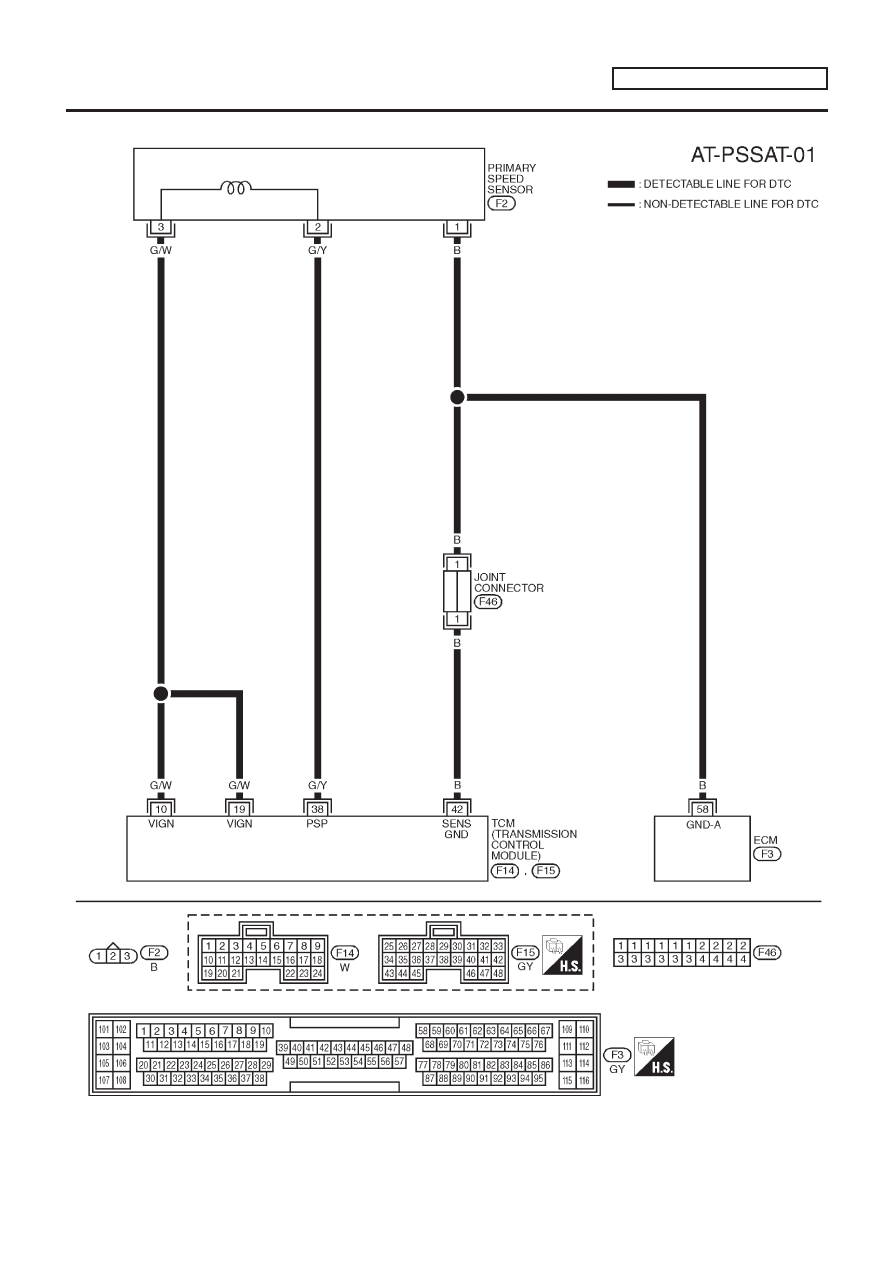
NLAT0255S02
YAT215
PRIMARY SPEED SENSOR
EXCEPT FOR EURO-OBD
Wiring Diagram — AT — VSSMTR (Cont’d)
AT-135
|
|
|
MODELS WITH ECM IN CABIN NLAT0255S02 YAT215 PRIMARY SPEED SENSOR EXCEPT FOR EURO-OBD Wiring Diagram — AT — VSSMTR (Cont’d) AT-135 |