Nissan Almera Tino V10 (2001 year). Manual - part 8
MODELS WITH ECM IN CABIN
NLAT0201S02
YAT216
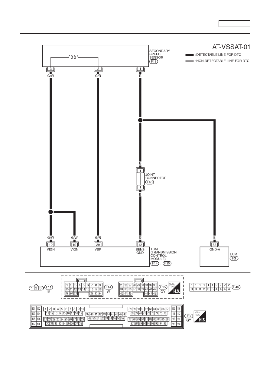
DTC P0720 VEHICLE SPEED SENSOR
(SECONDARY SPEED SENSOR)
EURO-OBD
Wiring Diagram — AT — VSSA/T (Cont’d)
AT-87
|
|
|
MODELS WITH ECM IN CABIN NLAT0201S02 YAT216 DTC P0720 VEHICLE SPEED SENSOR (SECONDARY SPEED SENSOR) EURO-OBD Wiring Diagram — AT — VSSA/T (Cont’d) AT-87 |