Nissan Almera Tino V10 (2001 year). Manual - part 6


  Index      Manuals     Nissan Almera Tino V10 (2001 year) - Service and Repair Manual


Search            copyright infringement  


Content      ..     4      5      6      7     ..


Nissan Almera Tino V10 (2001 year). Manual - part 6


SAT228K

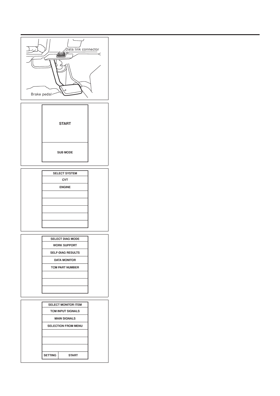
CONSULT-II Setting Procedure

NLAT0028S0402

1.

Turn ignition switch “OFF”.

2.

Connect CONSULT-II to data link connector which is located
in the left side lower dash panel.

SAT586J

3.

Turn ignition switch “ON”.

4.

Touch “START”.

SAT250K

5.

Touch “CVT”.

SAT252K

6.

Touch “DATA MONITOR”.

SAT253K

7.

Touch “MAIN SIGNALS” to set recording condition.

8.

See “Numerical Display”, “Barchart Display” or “Line Graph
Display”.

9.

Touch “START”.

TROUBLE DIAGNOSIS — BASIC INSPECTION

Road Test (Cont’d)

AT-55

SAT236K

10. When performing cruise test, touch “Store Data”.

SAT237K

11. After finishing cruise test part 1, touch “STOP”.

SAT254K

12. Touch “STORE”.

SAT608J

13. Touch “DISPLAY”.

SAT238K

14. Touch “PRINT”.
15. Check the monitor data printed out.
16. Continue cruise test part 2 and 3.

TROUBLE DIAGNOSIS — BASIC INSPECTION

Road Test (Cont’d)

AT-56

SAT417J

Without CONSULT-II

NLAT0028S0403

+

Throttle position sensor can be checked by voltage across
terminals 41 and 42 of TCM.
Refer to “Road Test”, AT-53.

TROUBLE DIAGNOSIS — BASIC INSPECTION

Road Test (Cont’d)

AT-57

SAT216J

TCM Terminals and Reference Value

NLAT0030

PREPARATION

NLAT0030S01

+

Measure voltage between each terminal and terminal 25 or 48
by following “TCM INSPECTION TABLE”.

TCM HARNESS CONNECTOR TERMINAL LAYOUT

NLAT0030S02

SAT403JA

TCM INSPECTION TABLE

NLAT0030S03

(Data are reference values.)

Terminal

No.

Wire color

Item

Condition

Judgement stan-

dard (Approx.)

1

R/W

Line pressure
solenoid valve

When releasing accelerator pedal
after warming up engine.

2.8V

When depressing accelerator pedal
fully after warming up engine.

1.4V

2

P/B

Line pressure
solenoid valve
(with dropping
resistor)

When releasing accelerator pedal
after warming up engine.

11.0V

When depressing accelerator pedal
fully after warming up engine.

4.0V

3

GY/R

Torque converter
clutch solenoid
valve

When CVT performs lock-up.

12.0V

When CVT does not perform lock-
up.

0V

5 *1

Y/R

DT1

6 *1

Y/G

DT2

7 *1

Y/L

DT3

8 *1

BR/W

DT5

9 *1

G/Y

DT4

10

G/W

Power source

When turning ignition switch to
“ON”.

Battery voltage

When turning ignition switch to
“OFF”.

0V

TROUBLE DIAGNOSIS — GENERAL DESCRIPTION

TCM Terminals and Reference Value

AT-58

Terminal

No.

Wire color

Item

Condition

Judgement stan-

dard (Approx.)

11

PU

Step motor A

Within 2 seconds after key switch “ON”, the time measurement by
using the pulse width measurement function (Hi level) of CON-
SULT-II.

+

CONSULT-II cable connected to data link connector.

+

This inspection cannot be measured by circuit tester.

30.0 msec

12

L/W

Step motor B

10.0 msec

13

OR/B

SPORT indicator
lamp

When SPORT indicator lamp illumi-
nates

0V

When SPORT indicator lamp does
not illuminate

Battery voltage

15 *1

PU

(EURO-OBD-II)

16

Y/PU

Closed throttle
position switch
(in throttle posi-
tion switch)

When releasing accelerator pedal
after warming up engine.
Refer to step 1 to 6 of
“Preparation”, “TCM Self-diagnostic
Procedure (No Tools)”, AT-28 
EURO-OBD/AT-35 — Except for
EURO-OBD.

Battery voltage

When depressing accelerator pedal
after warming up engine.
Refer to step 1 to 6 of
“Preparation”, “TCM Self-diagnostic
Procedure (No Tools)”, AT-28 
EURO-OBD/AT-35 — Except for
EURO-OBD.

0V

17

LG

Wide open
throttle position
switch
(in throttle posi-
tion switch)

When depressing accelerator pedal
more than half-way after warming
up engine.

Battery voltage

When releasing accelerator pedal
after warming up engine.

0V

18

BR

ABS control unit

When driving slowly.

Change 0V to
battery voltage

19

G/W

Power source

Same as No. 10

20

L/Y

Step motor C

Within 2 seconds after key switch “ON”, the time measurement by
using the pulse width measurement function (Hi level) of CON-
SULT-II.

+

CONSULT-II cable connected to data link connector.

+

This inspection cannot be measured by circuit tester.

30.0 msec

21

P/L

Step motor D

10.0 msec

22

P

Sport mode
switch

When SPORT mode switch in “ON”
position.

0V

When SPORT mode switch in
“OFF” position.

10V

23

SB

ABS control unit

When ABS operates.

0V

When ABS does not operate.

5.6 - 10.0V

TROUBLE DIAGNOSIS — GENERAL DESCRIPTION

TCM Terminals and Reference Value (Cont’d)

AT-59

Terminal

No.

Wire color

Item

Condition

Judgement stan-

dard (Approx.)

25

B

Ground

27

L

PNP switch “L”
position

When setting selector lever to “L”
position.

Battery voltage

When setting selector lever to other
positions.

0V

28

R/B

Power source
(Memory back-up)

or

When turning ignition switch to
“OFF”.

Battery voltage

When turning ignition switch to
“ON”.

Battery voltage

29

G/R

Secondary speed
sensor

When driving [D position, 20 km/h (12 MPH)], the pulse measure-
ment by using the pulse measurement function of CONSULT-II.

+

CONSULT-II cable connected to data link connector.

+

This inspection cannot be measured by circuit tester.

600 Hz

30 *2

G/B

(RX)

31 *2

GY/L

(TX)

32

R

Throttle position
sensor
(Power source)

When turning ignition switch to “ON” 4.5 - 5.5V

When turning ignition switch to
“OFF”

0V

34

W/G

PNP switch “D”
position

When setting selector lever to “D”
position.

Battery voltage

When setting selector lever to other
positions.

0V

35

G/W

PNP switch “R”
position

When setting selector lever to “R”
position.

Battery voltage

When setting selector lever to other
positions.

0V

36

G

PNP switch “N” or
“P” position

When setting selector lever to “N” or
“P” position.

Battery voltage

When setting selector lever to other
positions.

0V

37

W

CVT fluid pres-
sure sensor

When engine runs at idle speed.

1.0V

When engine runs at stoll speed.

4.0V

38

G/Y

Primary speed
sensor

When driving [L position, 20 km/h (12 MPH)], the pulse measure-
ment by using the pulse measurement function of CONSULT-II.

+

CONSULT-II cable connected to data link connector.

+

This inspection cannot be measured by circuit tester.

900 Hz

39

L/OR

Engine speed
signal

When engine runs at idle speed.

0.5 - 1.5V

TROUBLE DIAGNOSIS — GENERAL DESCRIPTION

TCM Terminals and Reference Value (Cont’d)

AT-60

Terminal

No.

Wire color

Item

Condition

Judgement stan-

dard (Approx.)

41

GY

Throttle position
sensor

When depressing accelerator pedal
slowly after warming up engine.
(Voltage rises gradually in response
to throttle position.)

Fully-closed
throttle: 0.5V
Fully-open
throttle: 4V

42

B

Throttle position
sensor
(Ground)

45

R/G

Stop lamp switch

When depressing accelerator pedal

Battery voltage

When releasing accelerator pedal

0V

46

R/L

CVT fluid pres-
sure sensor
(Power source)

4.5 - 5.5V

47

BR

CVT fluid tem-
perature sensor

When CVT fluid temperature is
20°C (68°F).

1.5V

When CVT fluid temperature is
80°C (176°F).

0.5V

48

B

Ground

*1: This terminal is connected to the ECM.
*2: These terminals are connected to the Data link connector for CONSULT-II.

TROUBLE DIAGNOSIS — GENERAL DESCRIPTION

TCM Terminals and Reference Value (Cont’d)

AT-61

Wiring Diagram — AT — MAIN

NLAT0031

MODELS WITH ECM IN ENGINE COMPARTMENT

NLAT0031S01

YAT173

TROUBLE DIAGNOSIS FOR POWER SUPPLY

Wiring Diagram — AT — MAIN

AT-62

MODELS WITH ECM IN CABIN

NLAT0031S03

YAT212

TROUBLE DIAGNOSIS FOR POWER SUPPLY

Wiring Diagram — AT — MAIN (Cont’d)

AT-63

TCM Terminals and Reference Value

NLAT0329

Remarks: Specification data are reference values.

Terminal

No.

Wire color

Item

Condition

Judgement stan-

dard (Approx.)

10

G/W

Power source

When turning ignition switch to
“ON”.

Battery voltage

When turning ignition switch to
“OFF”.

0V

19

G/W

Power source

Same as No. 10

25

B

Ground

28

R/B

Power source
(Memory back-up)

or

When turning ignition switch to
“OFF”.

Battery voltage

When turning ignition switch to
“ON”.

Battery voltage

48

B

Ground

TROUBLE DIAGNOSIS FOR POWER SUPPLY

TCM Terminals and Reference Value

AT-64

Diagnostic Procedure

NLAT0330

1

CHECK TCM POWER SOURCE

1. Turn ignition switch to “ON” position.

(Do not start engine.)

2. Check voltage between TCM terminals 10, 19, 28 and ground.

Voltage: Battery voltage

3. Turn ignition switch to “OFF” position.
4. Check voltage between TCM terminal 28 and ground.

Voltage: Battery voltage

SAT332J

OK or NG

OK

©

GO TO 2.

NG

©

Check the following items:

+

Harness for short or open between ignition switch and TCM terminals 10, 19 and 25
(Main harness)

+

Ignition switch and fuse
Refer to EL section (“POWER SUPPLY ROUTING”).

2

CHECK TCM GROUND CIRCUIT

1. Turn ignition switch to “OFF” position.
2. Disconnect TCM harness connector.
3. Check continuity between terminals 25, 48 and ground.

Continuity should exist.

SAT333J

If OK, check harness for short to ground and short to power.

OK or NG

OK

©

INSPECTION END

NG

©

Repair open circuit or short to ground or short to power in harness or connectors.

TROUBLE DIAGNOSIS FOR POWER SUPPLY

Diagnostic Procedure

AT-65

Description

NLAT0032

+

The PNP switch assembly includes a transmission range
switch.

+

The transmission range switch detects the selector lever posi-
tion and sends a signal to the TCM.

TCM TERMINALS AND REFERENCE VALUE

NLAT0032S01

Remarks: Specification data are reference values.

Terminal

No.

Wire color

Item

Condition

Judgement

standard

(Approx.)

27

L

PNP switch “L”
position

When setting selector lever to “L”
position.

Battery voltage

When setting selector lever to
other positions.

0V

34

W/G

PNP switch “D”
position

When setting selector lever to “D”
position.

Battery voltage

When setting selector lever to
other positions.

0V

35

G/W

PNP switch “R”
position

When setting selector lever to “R”
position.

Battery voltage

When setting selector lever to
other positions.

0V

36

G

PNP switch “N” or
“P” position

When setting selector lever to “N”
or “P” position.

Battery voltage

When setting selector lever to
other positions.

0V

ON BOARD DIAGNOSIS LOGIC

NLAT0032S02

Diagnostic trouble code

Malfunction is detected when ...

Check items (Possible cause)

: PNP SW/CIRC

TCM does not receive the correct voltage
signal from the switch based on the gear
position.

+

Harness or connectors
(The PNP switch circuit is open or
shorted.)

+

PNP switch

: P0705

: MI Code No. 0705

DTC P0705 PARK/NEUTRAL POSITION (PNP) SWITCH

EURO-OBD

Description

AT-66

SAT250K

SAT255K

DIAGNOSTIC TROUBLE CODE (DTC) CONFIRMATION
PROCEDURE

NLAT0032S03

CAUTION:

Always drive vehicle at a safe speed.
NOTE:
If “DIAGNOSTIC TROUBLE CODE CONFIRMATION PROCE-
DURE” has been previously conducted, always turn ignition
switch “OFF” and wait at least 5 seconds before conducting
the next test.
After the repair, perform the following procedure to confirm the
malfunction is eliminated.

With CONSULT-II

1)

Turn ignition switch “ON” and select “DATA MONITOR” mode
for “CVT” with CONSULT-II.

2)

Make sure that output voltage of CVT fluid temperature sen-
sor is within the range below.

FLUID TEMP SEN: 0.5 - 1.5V

If out of range, drive the vehicle to decrease the voltage
(warm up the fluid) or stop engine to increase the voltage
(cool down the fluid)

3)

Select “DATA MONITOR” mode for “ENGINE” with CONSULT-
II.

4)

Start engine and maintain the following conditions for at least
15 consecutive seconds.

VHCL SPEED SE: 10 km/h (6 MPH) or more
THRTL POS SEN: More than 1.0/8
Selector lever: D position
ENG SPEED: 450 rpm or more

If the check result is “NG”, go to “Diagnostic Procedure”, AT-70.

With GST

Follow the procedure “With CONSULT-II”.

DTC P0705 PARK/NEUTRAL POSITION (PNP) SWITCH

EURO-OBD

Description (Cont’d)

AT-67

Wiring Diagram — AT — PNP/SW

NLAT0199

MODELS WITH ECM IN ENGINE COMPARTMENT

NLAT0199S01

YAT174

DTC P0705 PARK/NEUTRAL POSITION (PNP) SWITCH

EURO-OBD

Wiring Diagram — AT — PNP/SW

AT-68

MODELS WITH ECM IN CABIN

NLAT0199S02

YAT213

DTC P0705 PARK/NEUTRAL POSITION (PNP) SWITCH

EURO-OBD

Wiring Diagram — AT — PNP/SW (Cont’d)

AT-69

Diagnostic Procedure

NLAT0033

1

CHECK PNP SWITCH CIRCUIT (With CONSULT-II)

With CONSULT-II

1. Turn ignition switch to “ON” position.

(Do not start engine.)

2. Select “TCM INPUT SIGNALS” in “DATA MONITOR” mode for “CVT” with CONSULT-II.

SAT250K

3. Read out “P/N”, “R”, “D” and “L” position switches moving selector lever to each position.

Check the signal of the selector lever position is indicated properly.

OK or NG

OK

©

GO TO 3.

NG

©

Check the following items:

+

PNP switch
Refer to “Component Inspection”, AT-72.

+

Harness for short or open between ignition switch and PNP switch (Main harness)

+

Harness for short or open between PNP switch and TCM (Main harness)

+

Ignition switch and fuse
Refer to EL section (“POWER SUPPLY ROUTING”).

2

CHECK PNP SWITCH CIRCUIT (Without CONSULT-II)

Without CONSULT-II

1. Turn ignition switch to “ON” position.

(Do not start engine.)

2. Check voltage between TCM terminals 27, 34, 35, 36 and ground while moving selector lever through each position.

Voltage:

B: Battery voltage
0: 0V

MTBL0312

OK or NG

OK

©

GO TO 3.

NG

©

Check the following items:

+

PNP switch
Refer to “Component Inspection”, AT-72.

+

Harness for short or open between ignition switch and PNP switch (Main harness)

+

Harness for short or open between PNP switch and TCM (Main harness)

+

Ignition switch and fuse
Refer to EL section (“POWER SUPPLY ROUTING”).

DTC P0705 PARK/NEUTRAL POSITION (PNP) SWITCH

EURO-OBD

Diagnostic Procedure

AT-70


Content      ..     4      5      6      7     ..