Nissan Almera Tino V10 (2001 year). Manual - part 3


  Index      Manuals     Nissan Almera Tino V10 (2001 year) - Service and Repair Manual


Search            copyright infringement  


Content      ..     1      2      3      4      ..


Nissan Almera Tino V10 (2001 year). Manual - part 3


AAT470A

+

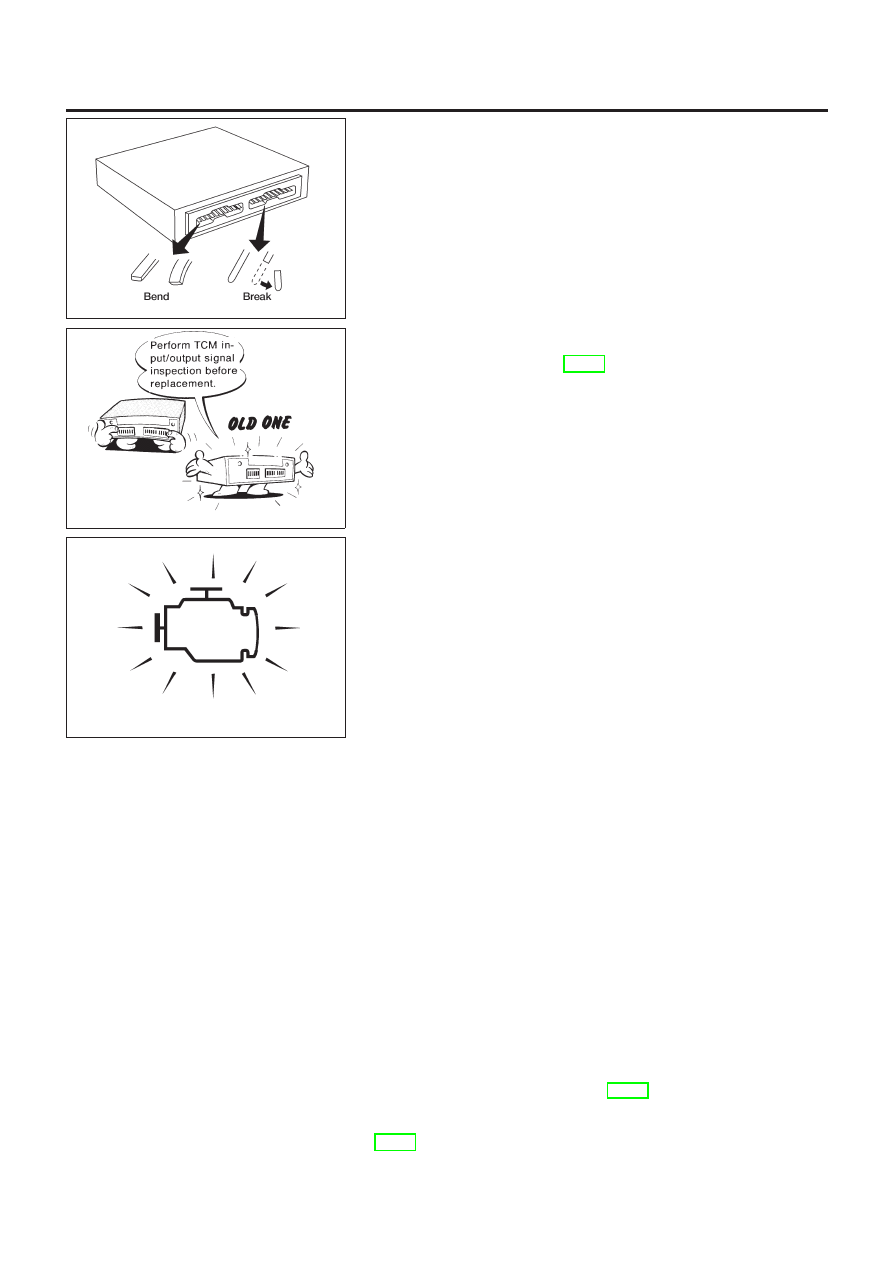
When connecting or disconnecting pin connectors into or
from TCM, take care not to damage pin terminals (bend or
break).
Make sure that there are not any bends or breaks on TCM
pin terminal, when connecting pin connectors.

MEF040DA

+

Before replacing TCM, perform TCM input/output signal
inspection and make sure whether TCM functions prop-
erly or not. (See page AT-58.)

SAT652J

+

After performing each TROUBLE DIAGNOSIS, perform
“DTC (Diagnostic Trouble Code) CONFIRMATION PROCE-
DURE”.
The DTC should not be displayed in the “DTC CONFIRMA-
TION PROCEDURE” if the repair is completed.

+

It is very important to perform functional tests whenever they
are indicated.

+

Extreme care should be taken to avoid damage to O-rings,
seals and gaskets when assembling.

+

When the CVT drain plug is removed, only some of the fluid is
drained. Old CVT fluid will remain in torque converter and CVT
fluid cooling system.
Always follow the procedures under “Changing CVT Fluid” in
the MA section when changing CVT fluid.

Service Notice or Precautions

NLAT0004

FAIL-SAFE

NLAT0004S01

The TCM has an electronic Fail-Safe (limp home mode). This allows the vehicle to be driven even if a major
electrical input/output device circuit is damaged.
Under Fail-Safe, the vehicle always runs even with a shift lever position of “L” or “D”. The customer may com-
plain of sluggish or poor acceleration.
When the ignition key is turned “ON” following Fail-Safe operation, SPORT indicator lamp blinks for about 8
seconds. [For “TCM SELF-DIAGNOSTIC PROCEDURE (No Tools)”, refer to AT-28.]
The blinking of the SPORT indicator lamp for about 8 seconds will appear only once and be cleared. The cus-
tomer may resume normal driving conditions.
Always follow the “WORK FLOW” (Refer to AT-44).

PRECAUTIONS

Precautions (Cont’d)

AT-7

The SELF-DIAGNOSIS results will be as follows:
The first SELF-DIAGNOSIS will indicate damage to the vehicle speed sensor or the revolution sensor.
During the next SELF-DIAGNOSIS, performed after checking the sensor, no damages will be indicated.

EURO-OBD SELF-DIAGNOSIS

NLAT0004S04

+

CVT self-diagnosis is performed by the TCM in combination with the ECM. The results can be read through
the blinking pattern of the SPORT indicator lamp. Refer to the table on AT-22 for the indicator used to dis-
play each self-diagnostic result.

+

The self-diagnostic results indicated by the MI are automatically stored in both the ECM and TCM memo-
ries.
Always perform the procedure “HOW TO ERASE DTC” on AT-19 to complete the repair and avoid
unnecessary blinking of the MI.

For details of EURO-OBD, refer to EC section (“ON BOARD DIAGNOSTIC SYSTEM DESCRIPTION”).

+

Certain systems and components, especially those related to EURO-OBD, may use a new style
slide-locking type harness connector.
For description and how to disconnect, refer to EL section, “Description”, “HARNESS CONNEC-
TOR”.

Wiring Diagrams and Trouble Diagnoses

NLAT0005

When you read wiring diagrams, refer to the following:

+

“HOW TO READ WIRING DIAGRAMS” in GI section

+

“POWER SUPPLY ROUTING” for power distribution circuit in EL section

When you perform trouble diagnoses, refer to the following:

+

“HOW TO FOLLOW TEST GROUPS IN TROUBLE DIAGNOSES” in GI section

+

“HOW TO PERFORM EFFICIENT DIAGNOSIS FOR AN ELECTRICAL INCIDENT” in GI section

PRECAUTIONS

Service Notice or Precautions (Cont’d)

AT-8

Special Service Tools

NLAT0006

Tool number
Tool name

Description

ST2505S001
Oil pressure gauge set
1 ST25051001
Oil pressure gauge
2 ST25052000
Hose
3 ST25053000
Joint pipe
4 ST25054000
Adapter
5 ST25055000
Adapter

NT097

Measuring line pressure and governor pressure

KV31103000
Drift

NT105

Installing differential side oil seal
(Use with ST35325000)
a: 59 mm (2.32 in) dia.
b: 49 mm (1.93 in) dia.

ST35325000
Drift

NT417

Installing differential side oil seal
(Use with KV31103000)
a: 215 mm (8.46 in)
b: 25 mm (0.98 in) dia.
c: M12 x 1.5P

PREPARATION

Special Service Tools

AT-9

SMA146B

Checking CVT Fluid

NLAT0243

1.

Check for fluid leakage.

SAT282K

2.

Check fluid level.
Fluid level should be check using “HOT” range on A/T fluid
level gauge at fluid temperatures of 50 to 80°C (122 to 176°F)
after vehicle has been driven approximately 10 minutes in
urban areas after engine is warmed up. But it can be checked
at fluid temperatures of 30 to 50°C (86 to 122°F) using “COLD”
range on A/T fluid level gauge for reference after engine is
warmed up and before driving. However, fluid level must be
rechecked using “HOT” range.

a.

Park vehicle on level surface and set parking brake.

b.

Start engine and then move selector lever through reach gear
range, ending in “P”.

c.

Check fluid level with engine idling.

d.

Remove A/T fluid level gauge and wipe it clean with lint-free
paper.

e.

Re-insert A/T fluid level gauge into charging pipe as far as it
will go.

f.

Remove A/T fluid level gauge and note reading. If level is at
low side of either range, add fluid through the speedometer
cable hole.
Use genuine NISSAN CVT fluid (NS-1) or exact equivalent.

CAUTION:

Do not overfill.

CAUTION:

SMA051D

Firmly fix the A/T fluid level gauge using a lip attached to the
fluid charging pipe.

CVT FLUID

Checking CVT Fluid

AT-10

SMA853B

3.

Check fluid condition.
Check fluid for contamination. If fluid is very dark, smells
burned or contains frictional material check operation of CVT.
Refer to section AT for checking operation of CVT.

SMA294C

Changing CVT Fluid

NLAT0244

1.

Warm up CVT fluid by driving the vehicle for 10 minutes.

2.

Drain CVT fluid from radiator cooler hose (return side) and refill
with new CVT fluid at charging pipe with the engine running at
idle speed.

3.

Refill until new CVT fluid comes out from radiator cooler hose
(return side).
About 30 to 50% extra fluid will be required for this procedure.

Fluid capacity

Hyper CVT: Approx. 8.1

!

(7-1/8 lmp qt)

Drain plug:

: 23 - 27 N·m (2.4 - 2.8 kg-m, 18 - 20 ft-lb)

CAUTION:

Use genuine NISSAN CVT fluid (NS-1) or exact equivalent.
4.

Check fluid level and condition.

CVT FLUID

Checking CVT Fluid (Cont’d)

AT-11

CVT Electrical Parts Location

NLAT0008

SAT226K

OVERALL SYSTEM

CVT Electrical Parts Location

AT-12

Circuit Diagram

NLAT0009

YAT172

OVERALL SYSTEM

Circuit Diagram

AT-13

Cross-sectional View — RE0F06A

NLAT0011

SAT668J

OVERALL SYSTEM

Cross-sectional View — RE0F06A

AT-14

Control System

=NLAT0014

OUTLINE

NLAT0014S01

The CVT senses vehicle operating conditions through various sensors. It always controls the optimum shift
position and reduces shifting and lock-up shocks.

SWITCHES AND SENSORS

c

TCM

c

ACTUATORS

PNP switch
Throttle position sensor
Closed throttle position switch
Wide open throttle position
switch
Engine speed signal
CVT fluid temperature sensor
CVT fluid pressure sensor
Primary speed sensor
Secondary speed sensor
Stop lamp switch
SPORT mode switch
ABS control unit

Shift control
Line pressure control
Lock-up control
Fail-safe control
Self-diagnosis
CONSULT-II communication line
control
Duet-EA control
On board diagnosis

Step motor
Torque converter clutch solenoid
valve
Line pressure solenoid valve
SPORT indicator lamp

OVERALL SYSTEM

Control System

AT-15

CONTROL SYSTEM

NLAT0014S02

SAT227K

OVERALL SYSTEM

Control System (Cont’d)

AT-16

TCM FUNCTION

=NLAT0014S03

The function of the TCM is to:

+

Receive input signals sent from various switches and sensors.

+

Determine required line pressure, shifting point and lock-up operation.

+

Send required output signals to the step motor and the respective solenoids.

INPUT/OUTPUT SIGNAL OF TCM

NLAT0014S04

Switches, sensors and actuators

Function

Input

PNP switch

Detects select lever position and sends a signal to TCM.

Throttle position sensor

Detects throttle valve position and sends a signal to TCM.

Closed throttle position switch

Detects throttle valve’s fully-closed position and sends a signal to TCM.

Wide open throttle position switch

Detects a throttle valve position of greater than 1/2 of full throttle and
sends a signal to TCM.

Engine speed signal

From ECM.

CVT fluid temperature sensor

Detects transmission fluid temperature and sends a signal to TCM.

CVT fluid pressure sensor

Detects transmission fluid pressure and sends a signal to TCM.

Primary speed sensor

Detects primary pulley rpm and sends a signal to TCM.

Secondary speed sensor

Detects secondary pulley rpm and sends a signal to TCM.

Stop lamp switch

Sends a signal to the TCM relaying the operation condition of the brake
pedal.

SPORT mode switch

Sends a signal to the TCM relaying the operation condition of the SPORT
mode switch.

ABS control unit

Sends a signal to the TCM operation condition of the ABS.

Output

Step motor

Regulates pulley position in relation to a signal sent from TCM.

Line pressure solenoid valve

Regulates (or decreases) line pressure suited to driving conditions in rela-
tion to a signal sent from TCM.

Torque converter clutch solenoid
valve

Regulates (or decreases) lock-up pressure suited to driving conditions in
relation to a signal sent from TCM.

SPORT indicator lamp

Shows the operation condition of the SPORT mode switch.

OVERALL SYSTEM

Control System (Cont’d)

AT-17

Introduction

NLAT0017

The CVT system has two self-diagnostic systems.
The first is the emission-related on board diagnostic system (EURO-OBD) performed by the TCM in combi-
nation with the ECM. The malfunction is indicated by the MI (malfunction indicator) and is stored as a DTC in
the ECM memory but not the TCM memory.
The second is the TCM original self-diagnosis indicated by the CVT indicator (warning) lamp or SPORT indi-
cator lamp. The malfunction is stored in the TCM memory. The detected items are overlapped with EURO-
OBD self-diagnostic items. For detail, refer to AT-28.

EURO-OBD Function for CVT System

NLAT0018

The ECM provides emission-related on board diagnostic (EURO-OBD) functions for the CVT system. One
function is to receive a signal from the TCM used with EURO-OBD-related parts of the CVT system. The sig-
nal is sent to the ECM when a malfunction occurs in the corresponding EURO-OBD-related part. The other
function is to indicate a diagnostic result by means of the MI (malfunction indicator) on the instrument panel.
Sensors, switches and solenoid valves are used as sensing elements.
The MI automatically illuminates in Two Trip Detection Logic when a malfunction is sensed in relation to CVT
system parts.

EURO-OBD Diagnostic Trouble Code (DTC)

NLAT0020

HOW TO READ DTC AND 1ST TRIP DTC

NLAT0020S01

DTC and 1st trip DTC can be read by the following methods.
1. (

No Tools) The number of blinks of the malfunction indicator in the Diagnostic Test Mode II (Self-Di-

agnostic Results) Examples: 0705, 0710, 0715, 0720, etc. For details, refer to EC section [“Malfunction
Indicator (MI)”, “ON BOARD DIAGNOSTIC SYSTEM DESCRIPTION”].
These DTCs are controlled by NISSAN.

2. (

with CONSULT-II or

GST) CONSULT-II or GST (Generic Scan Tool) Examples: P0705, P0710,

P0720, P0725, etc.
These DTCs are prescribed by ISO15031-6.
(CONSULT-II also displays the malfunctioning component or system.)

+

1st trip DTC No. is the same as DTC No.

+

Output of the diagnostic trouble code indicates that the indicated circuit has a malfunction.
However, in case of the Mode II and GST they do not indicate whether the malfunction is still
occurring or occurred in the past and returned to normal.
CONSULT-II can identify them as shown below. Therefore, using CONSULT-II (if available) is rec-
ommended.

A sample of CONSULT-II display for DTC is shown at left. DTC or 1st trip DTC of a malfunction is displayed
in SELF-DIAGNOSTIC RESULTS mode for “ENGINE” with CONSULT-II. Time data indicates how many times
the vehicle was driven after the last detection of a DTC.

SAT250K

If the DTC is being detected currently, the time data will be “0”.

ON BOARD DIAGNOSTIC SYSTEM DESCRIPTION

EURO-OBD

Introduction

AT-18

SAT015K

If a 1st trip DTC is stored in the ECM, the time data will be “1t”.

SAT016K

Freeze Frame Data and 1st Trip Freeze Frame Data

NLAT0020S0101

The ECM has a memory function, which stores the driving condition such as fuel system status, calculated
load value, engine coolant temperature, short term fuel trim, long term fuel trim, engine speed and vehicle
speed at the moment the ECM detects a malfunction.
Data which are stored in the ECM memory, along with the 1st trip DTC, are called 1st trip freeze frame data,
and the data, stored together with the DTC data, are called freeze frame data and displayed on CONSULT-II
or GST. The 1st trip freeze frame data can only be displayed on the CONSULT-II screen, not on the GST. For
detail, refer to EC section (“CONSULT-II”, “ON BOARD DIAGNOSTIC SYSTEM DESCRIPTION”).
Only one set of freeze frame data (either 1st trip freeze frame data of freeze frame data) can be stored in the
ECM. 1st trip freeze frame data is stored in the ECM memory along with the 1st trip DTC. There is no prior-
ity for 1st trip freeze frame data and it is updated each time a different 1st trip DTC is detected. However, once
freeze frame data (2nd trip detection/MI on) is stored in the ECM memory, 1st trip freeze frame data is no
longer stored. Remember, only one set of freeze frame data can be stored in the ECM.
The ECM has the following priorities to update the data.

Prior-

ity

Items

1

Freeze frame data

Misfire — DTC: P0300 - P0306 (0300 - 0306)
Fuel Injection System Function — DTC: P0171 (0171), P0172 (0172), P0174 (0174), P0175
(0175)

2

Except the above items (Includes CVT related items)

3

1st trip freeze frame data

Both 1st trip freeze frame data and freeze frame data (along with the DTCs) are cleared when the ECM
memory is erased.

HOW TO ERASE DTC

NLAT0020S02

The diagnostic trouble code can be erased by CONSULT-II, GST or ECM DIAGNOSTIC TEST MODE as
described following.

+

If the battery terminal is disconnected, the diagnostic trouble code will be lost within 24 hours.

+

When you erase the DTC, using CONSULT-II or GST is easier and quicker than switching the mode
selector on the ECM.

ON BOARD DIAGNOSTIC SYSTEM DESCRIPTION

EURO-OBD

EURO-OBD Diagnostic Trouble Code (DTC) (Cont’d)

AT-19

The following emission-related diagnostic information is cleared from the ECM memory when erasing DTC
related to EURO-OBD. For details, refer to EC section (“Emission-related Diagnostic Information”, “ON BOARD
DIAGNOSTIC SYSTEM DESCRIPTION”).

+

Diagnostic trouble codes (DTC)

+

1st trip diagnostic trouble codes (1st trip DTC)

+

Freeze frame data

+

1st trip freeze frame data

+

System readiness test (SRT) codes

+

Test values

+

Distance traveled while MI is activated

+

Others

HOW TO ERASE DTC (WITH CONSULT-II)

NLAT0020S03

+

If a DTC is displayed for both ECM and TCM, it needs to be erased for both ECM and TCM.

1. If the ignition switch stays “ON” after repair work, be sure to turn ignition switch “OFF” once. Wait at least

5 seconds and then turn it “ON” (engine stopped) again.

2. Turn CONSULT-II “ON” and touch “CVT”.
3. Touch “SELF-DIAG RESULTS”.
4. Touch “ERASE”. (The DTC in the TCM will be erased.) Then touch “BACK” twice.
5. Touch “ENGINE”.
6. Touch “SELF-DIAG RESULTS”.
7. Touch “ERASE”. (The DTC in the ECM will be erased.)

SAT251K

ON BOARD DIAGNOSTIC SYSTEM DESCRIPTION

EURO-OBD

EURO-OBD Diagnostic Trouble Code (DTC) (Cont’d)

AT-20

HOW TO ERASE DTC (WITH GST)

=NLAT0020S04

1. If the ignition switch stays “ON” after repair work, be sure to turn ignition switch “OFF” once. Wait at least

5 seconds and then turn it “ON” (engine stopped) again.

2. Perform “EURO-OBD SELF-DIAGNOSTIC PROCEDURE (No Tools)”. Refer to AT-28. (The engine

warm-up step can be skipped when performing the diagnosis only to erase the DTC.)

3. Select Mode 4 with Generic Scan Tool (GST). For details, refer to EC section “Generic Scan Tool (GST)”.

HOW TO ERASE DTC (NO TOOLS)

NLAT0020S05

1. If the ignition switch stays “ON” after repair work, be sure to turn ignition switch “OFF” once. Wait at least

5 seconds and then turn it “ON” (engine stopped) again.

2. Perform “TCM SELF-DIAGNOSTIC PROCEDURE (No Tools)”. Refer to AT-28. (The engine warm-up step

can be skipped when performing the diagnosis only to erase the DTC.)

3. Change the diagnostic test mode from Mode II to Mode I by turning the mode selector on the ECM.

Refer to EC section “HOW TO SWITCH DIAGNOSTIC TEST MODES”.

SAT652J

Malfunction Indicator (MI)

NLAT0021

1.

The malfunction indicator will light up when the ignition switch
is turned ON without the engine running. This is for checking
the lamp.

+

If the malfunction indicator lamp does not light up, refer to EL
section (“Warning Lamps/System Description”, “WARNING
LAMPS AND CHIME”).
(Or see MI & Data Link Connectors in EC section.)

2.

When the engine is started, the malfunction indicator lamp
should go off.
If the lamp remains on, the on board diagnostic system has
detected an emission-related (EURO-OBD) malfunction. For
detail, refer to EC section (“ON BOARD DIAGNOSTIC SYS-
TEM DESCRIPTION”).

CONSULT-II

NLAT0022

After performing “SELF-DIAGNOSTIC PROCEDURE (WITH CON-
SULT-II)” (AT-22), place check marks for results on the “DIAGNOS-
TIC WORKSHEET”, AT-43. Reference pages are provided follow-
ing the items.
NOTICE:

+

Additional CONSULT-II information can be found in the Opera-
tion Manual supplied with the CONSULT-II unit.

ON BOARD DIAGNOSTIC SYSTEM DESCRIPTION

EURO-OBD

EURO-OBD Diagnostic Trouble Code (DTC) (Cont’d)

AT-21

SAT250K

SELF-DIAGNOSTIC PROCEDURE (WITH CONSULT-II)

NLAT0022S02

1.

Turn on CONSULT-II and touch “ENGINE” for EURO-OBD
detected items or touch “CVT” for TCM self-diagnosis.
If CVT is not displayed, check TCM power supply and ground
circuit. Refer to AT-58. If result is NG, refer to EL section
(“POWER SUPPLY ROUTING”).

SAT987J

2.

Touch “SELF-DIAG RESULTS”.
Display shows malfunction experienced since the last erasing
operation.
CONSULT-II performs REAL TIME DIAGNOSIS.
Also, any malfunction detected while in this mode will be dis-
played at real time.

SELF-DIAGNOSTIC RESULT TEST MODE

NLAT0022S03

Detected items
(Screen terms for CONSULT-II, “SELF-
DIAG RESULTS” test mode)

Malfunction is detected when ...

TCM self-diagnosis

EURO-OBD (DTC)

Available by

SPORT

indicator lamp

“CVT” on CON-

SULT-II

Available by

malfunction

indicator*2,

“ENGINE” on CON-

SULT-II or GST

“CVT”

“ENGINE”

PNP switch circuit

+

TCM does not receive the correct volt-
age signal (based on the gear posi-
tion) from the switch.

P0705

PNP SW/CIRCUIT

PNP SW/CIRC

Primary speed sensor

+

TCM does not receive the proper volt-
age signal from the sensor.

X

P0715

I/P PULLY SPD SIG

PRI SPEED SIG/
CIRC

Output pulley speed signal

+

TCM does not receive the proper volt-
age signal from the sensor.

X

P0720

O/P PULLY SPD
SIG

VEH SPD SEN/CIR
A/T

T/C clutch solenoid valve

+

TCM detects an improper voltage
drop when it tries to operate the sole-
noid valve.

X

P0740

T/C CLUTCH
SOL/V

TCC SOLENOID/
CIRC

Line pressure solenoid valve

+

TCM detects an improper voltage
drop when it tries to operate the sole-
noid valve.

X

P0745

LINE PRESSURE
S/V

L/PRESS SOL/
CIRC

Throttle position sensor

+

TCM receives an excessively low or
high voltage from the sensor.

X

P1705

THROTTLE POSI
SEN

TP SEN/CIRC A/T

ON BOARD DIAGNOSTIC SYSTEM DESCRIPTION

EURO-OBD

CONSULT-II (Cont’d)

AT-22


Content      ..     1      2      3      4      ..