Nissan Pathfinder (2008 year). Manual - part 167
HORN FUNCTION
DLK-237
< COMPONENT DIAGNOSIS >
[WITHOUT INTELLIGENT KEY SYSTEM]
C
D
E
F
G
H
I
J
L
M
A
B
DLK
N
O
P
3.
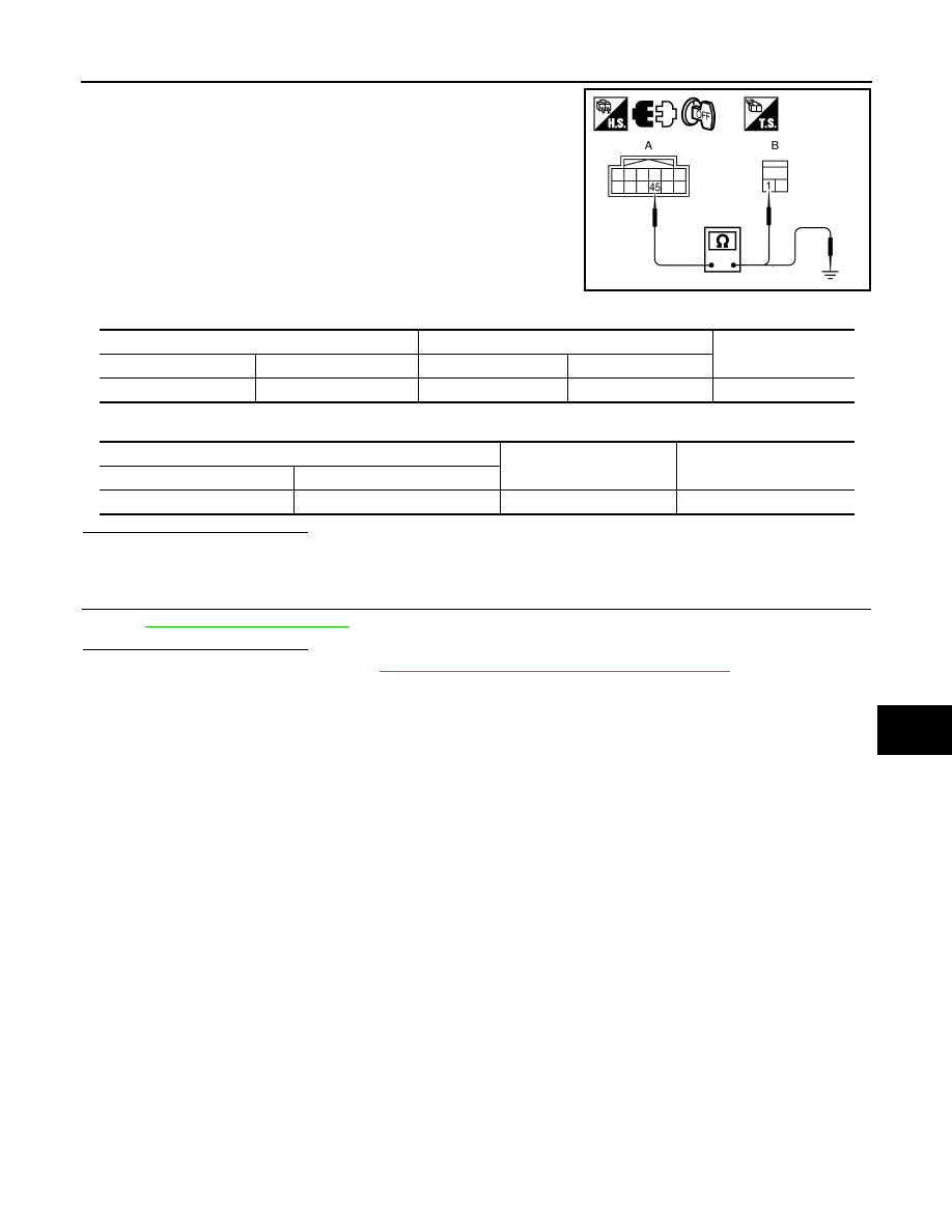
Check continuity between IPDM E/R harness connector and
horn relay harness connector.
4.
Check continuity between IPDM E/R harness connector and ground.
Is the inspection result normal?
YES
>> GO TO 4.
NO
>> Repair or replace harness.
4.
CHECK INTERMITTENT INCIDENT
GI-51, "Intermittent Incident"
.
Is the inspection result normal?
YES
>> Replace IPDM E/R. Refer to
PCS-30, "Removal and Installation of IPDM E/R"
.
NO
>> Repair or replace the malfunctioning part.
WIIA1252E
IPDM E/R
Horn relay
Continuity
Connector
Terminal
Connector
Terminal
A: E122
45
B: H-1
1
Yes
IPDM E/R
Ground
Continuity
Connector
Terminal
E122
45
Ground
No