Nissan Pathfinder (2008 year). Manual - part 165


  Index      Manuals     Nissan Pathfinder (2008 year) - Service and Repair Manual


Search            copyright infringement  


Content      ..     163      164      165      166     ..


Nissan Pathfinder (2008 year). Manual - part 165


KEY CYLINDER SWITCH

DLK-221

< COMPONENT DIAGNOSIS >

[WITHOUT INTELLIGENT KEY SYSTEM]

C

D

E

F

G

H

I

J

L

M

A

B

DLK

N

O

P

KEY CYLINDER SWITCH

Description

INFOID:0000000001728472

The main power window and door lock/unlock switch detects condition of the door key cylinder switch and
transmits to BCM as the LOCK or UNLOCK signal. 

Component Function Check

INFOID:0000000001728473

1.

CHECK DOOR KEY CYLINDER SWITCH INPUT SIGNAL

Check "KEY CYL LK-SW" AND "KEY CYL UN-SW" in DATA MONITOR mode for “POWER DOOR LOCK
SYSTEM” with CONSULT-III.

Is the inspection result normal?

YES

>> Key cylinder switch is OK.

NO

>> Refer to 

DLK-221, "Diagnosis Procedure"

.

Diagnosis Procedure

INFOID:0000000001728474

1.

CHECK DOOR KEY CYLINDER SWITCH LH

With CONSULT-III

Check front door lock assembly LH (key cylinder switch) ("KEY CYL LK-SW") and ("KEY CYL UN-SW) in
DATA MONITOR mode with CONSULT–III.
• When key inserted in left front key cylinder is turned to LOCK:

• When key inserted in left front key cylinder is turned to UNLOCK:
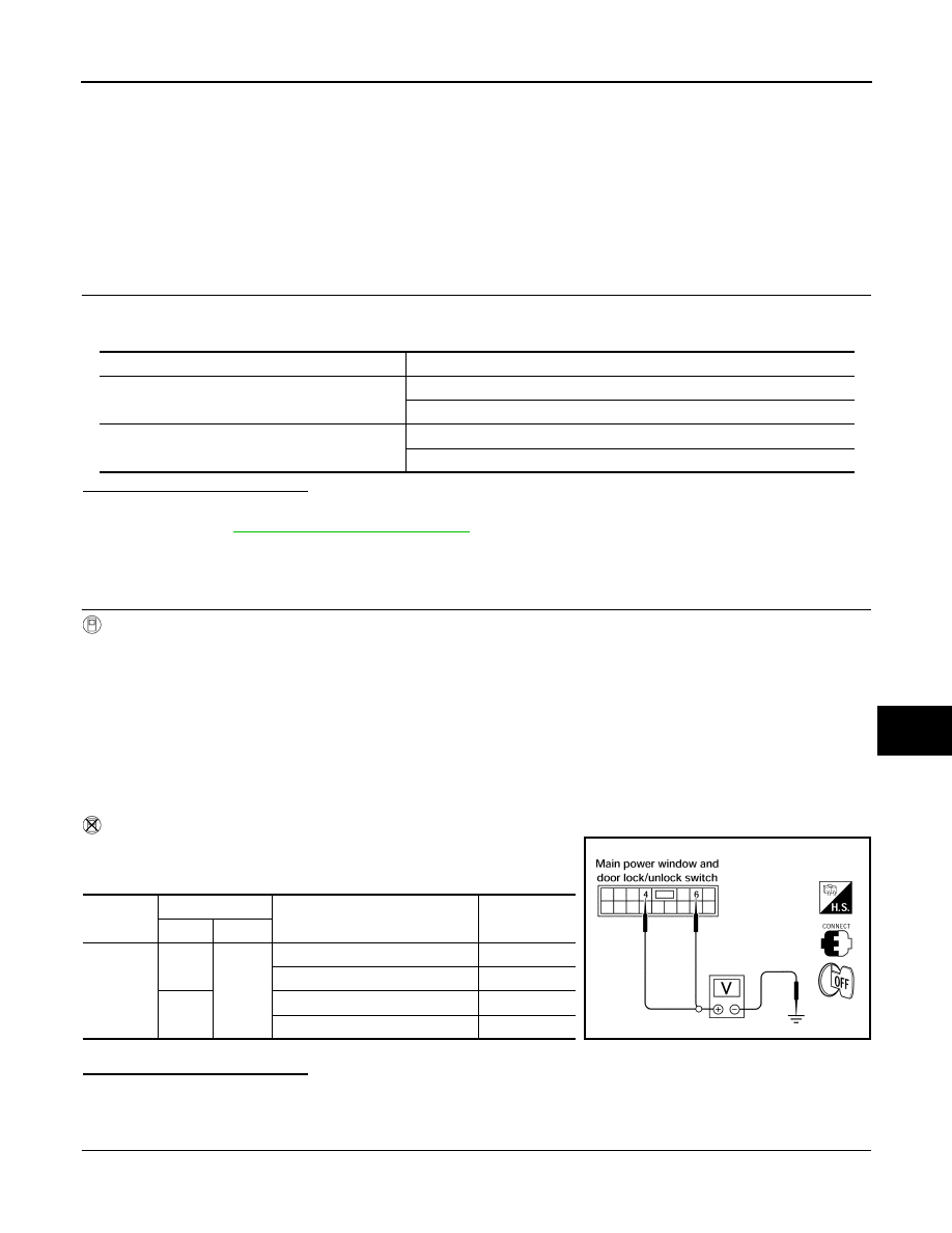
Without CONSULT-III

Check voltage between main power window and door lock/unlock
switch connector D7 terminals 4, 6 and ground.

Is the inspection result normal?

YES

>> Key cylinder switch signal is OK.

NO

>> GO TO 2.

2.

CHECK DOOR KEY CYLINDER SWITCH LH GROUND HARNESS

1.

Turn ignition switch OFF.

2.

Disconnect front door lock assembly LH (key cylinder switch).

Monitor item

Condition

KEY CYL LK-SW

Lock

: ON

Neutral / Unlock

: OFF

KEY CYL UN-SW

Unlock

: ON

Neutral / Lock

: OFF

KEY CYL LK-SW

: ON

KEY CYL UN-SW

: ON

Connector

Terminals

Condition of left front key cylinder

Voltage (V)

(Approx.)

(+)

(–)

D7

4

Ground

Neutral/Unlock

5

Lock

0

6

Neutral/Lock

5

Unlock

0

LIIA0566E

DLK-222

< COMPONENT DIAGNOSIS >

[WITHOUT INTELLIGENT KEY SYSTEM]

KEY CYLINDER SWITCH

3.

Check continuity between front door lock assembly LH (key cyl-
inder switch) connector (A) D14 terminal 4 and body ground.

Is the inspection result normal?

YES

>> GO TO 3.

NO

>> Repair or replace harness.

3.

CHECK DOOR KEY CYLINDER SWITCH LH

Check continuity between front door lock assembly LH (key cylinder
switch) terminals.

Is the inspection result normal?

YES

>> GO TO 4.

NO

>> Replace front door lock assembly LH (key cylinder switch). Refer to 

DLK-313, "Removal and

Installation"

.

4.

CHECK DOOR KEY CYLINDER HARNESS

Check continuity between main power window and door lock/unlock
switch connector (A) D7 terminals 4, 6 and front door lock assembly
LH (key cylinder switch) connector (B) D14 terminals 3, 5 and body
ground. 

Is the inspection result normal?

YES

>> Replace main power window and door lock/unlock switch.

NO

>> Repair or replace harness.

Connector

Terminals

Continuity

D14

4 – Ground

Yes

ALKIA1186ZZ

Terminals

Condition

Continuity

3 – 4

Key is turned to LOCK or neutral.

No

Key is turned to UNLOCK.

Yes

4 – 5

Key is turned to UNLOCK or neutral.

No

Key is turned to LOCK.

Yes

ALKIA1183ZZ

Connector

Terminals

Connector

Terminals

Continuity

A: Main 

power win-

dow and 

door lock/

unlock 

switch

4

B:  Front 

door lock 

assembly 

LH (key 
cylinder 

switch)

5

Yes

6

3

Yes

4, 6

Ground

No

ALKIA1184ZZ

FRONT DOOR LOCK ACTUATOR LH (DOOR UNLOCK SENSOR)

DLK-223

< COMPONENT DIAGNOSIS >

[WITHOUT INTELLIGENT KEY SYSTEM]

C

D

E

F

G

H

I

J

L

M

A

B

DLK

N

O

P

FRONT DOOR LOCK ACTUATOR LH (DOOR UNLOCK SENSOR)

Description - RF Door

INFOID:0000000001728475

Detects door lock condition of passenger door.

Diagnosis Procedure - RF Door

INFOID:0000000001728477

1.

CHECK LOCK SENSOR POWER SUPPLY

Check voltage between back door control unit connector terminal 5 and ground.

Is the inspection result normal?

YES

>> Front door lock assembly RH (door lock sensor) is OK.

NO

>> GO TO 2.

2.

CHECK LOCK SENSOR CIRCUIT

1.

Turn ignition switch OFF.

2.

Disconnect back door control unit and front door lock assembly
RH (door lock sensor) connector.

3.

Check continuity between back door control unit harness con-
nector (A) D509 terminal 5 and front door lock assembly RH
(door lock sensor) harness connector (B) D103 terminal 1.

4.

Check continuity between back door control unit harness con-
nector (A) D509 terminal 5 and ground.

Is the inspection result normal?

YES

>> GO TO 3.

NO

>> Repair or replace harness between back door control unit and front door lock assembly RH (door

lock sensor).

3.

CHECK LOCK SENSOR GROUND CIRCUIT

Check continuity between front door lock assembly RH (door lock sensor) harness connector D103 terminal 3
and ground.

Is the inspection result normal?

YES

>> GO TO 4.

NO

>> Repair or replace harness.

4.

CHECK BACK DOOR CONTROL UNIT OUTPUT SIGNAL

1.

Connect back door control unit harness connector.

2.

Check voltage between back door control unit harness connector D509 terminal 5 and ground.

Connector

Terminals

Condition

Voltage (V)

(Approx.)

(+)

(-)

D509

5

Ground

Passenger side door lock is locked

Battery 
voltage

Passenger side door lock is unlocked

0

ALKIA1247ZZ

5 – 1

: Continuity should exist.

5 – Ground

: Continuity should not exist.

ALKIA1248ZZ

3 – Ground

: Continuity should exist.

ALKIA1249ZZ

DLK-224

< COMPONENT DIAGNOSIS >

[WITHOUT INTELLIGENT KEY SYSTEM]

FRONT DOOR LOCK ACTUATOR LH (DOOR UNLOCK SENSOR)

Is the inspection result normal?

YES

>> Refer to 

DLK-224, "Component Inspection - RF Door"

.

NO

>> Replace back door control unit. Refer to 

DLK-317,

"Component Structure"

.

Component Inspection - RF Door

INFOID:0000000001728478

1.

CHECK DOOR LOCK SENSOR

Check door lock sensor.

Is the inspection result normal?

YES

>> INSPECTION END.

NO

>> Replace front lock assembly RH (door lock sensor). Refer to 

DLK-313, "Removal and Installation"

.

5 – Ground

: Battery voltage

WIIA1193E

ALKIA1250ZZ

Terminal

Front door lock assembly RH condition

Continuity

Front door lock assembly RH

1

3

Unlocked

Yes

Locked

No

DOOR LOCK ACTUATOR

DLK-225

< COMPONENT DIAGNOSIS >

[WITHOUT INTELLIGENT KEY SYSTEM]

C

D

E

F

G

H

I

J

L

M

A

B

DLK

N

O

P

DOOR LOCK ACTUATOR

DRIVER SIDE

DRIVER SIDE : Description

INFOID:0000000001728487

Locks/unlocks the door with the signal from BCM.

DRIVER SIDE : Component Function Check

INFOID:0000000001728488

1.

CHECK FUNCTION

1.

Use CONSULT-III to perform Active Test "DOOR LOCK".

2.

Touch “ALL LOCK” or “ALL UNLOCK” to check that it works normally.

Is the inspection result normal?

YES

>> Door lock actuator is OK.

NO

>> Refer to 

DLK-225, "DRIVER SIDE : Diagnosis Procedure"

.

DRIVER SIDE : Diagnosis Procedure

INFOID:0000000001728489

1.

CHECK DOOR LOCK ACTUATOR SIGNAL

1.

Turn ignition switch OFF.

2.

Check voltage between BCM connector M20 terminals 59, 65
and ground.

Is the inspection result normal?

YES

>> GO TO 2.

NO

>> GO TO 3.

2.

CHECK DOOR LOCK ACTUATOR HARNESS

1.

Disconnect BCM and front door lock assembly LH (actuator).

2.

Check continuity between BCM connector (A) M20 terminals 59,
65 and front door lock assembly LH (actuator) connector (B)
D14 terminals 1, 2. 

Is the inspection result normal?

YES

>> Replace front door lock assembly LH (actuator).

NO

>> Repair or replace harness.

3.

CHECK DOOR LOCK ACTUATOR HARNESS

1.

Disconnect BCM and front door lock assembly LH (actuator).

Connector

Terminals

Condition

Voltage (V)

(Approx.)

(+)

(-)

M20

59

Ground

Driver door lock/unlock 
switch is turned to UN-
LOCK

 Battery voltage

65

Driver door lock/unlock 
switch is turned to LOCK

 Battery voltage

LIIA1046E

Connector

Terminals

Connector

Terminals

Continuity

M20

59

D14

2

Yes

65

1

ALKIA1191ZZ

DLK-226

< COMPONENT DIAGNOSIS >

[WITHOUT INTELLIGENT KEY SYSTEM]

DOOR LOCK ACTUATOR

2.

Check continuity between BCM connector M20 terminals 59, 65
and ground.

Is the inspection result normal?

YES

>> Replace BCM. Refer to 

BCS-54, "Removal and Installation"

.

NO

>> Repair or replace harness.

PASSENGER SIDE

PASSENGER SIDE : Description

INFOID:0000000001728490

Locks/unlocks the door with the signal from BCM.

PASSENGER SIDE : Component Function Check

INFOID:0000000001728491

1.

CHECK FUNCTION

1.

Use CONSULT-III to perform Active Test DOOR LOCK.

2.

Touch “ALL LOCK” or “ALL UNLOCK” to check that it works normally.

Is the inspection result normal?

YES

>> Door lock actuator is OK.

NO

>> Refer to 

DLK-226, "PASSENGER SIDE : Diagnosis Procedure"

.

PASSENGER SIDE : Diagnosis Procedure

INFOID:0000000001728492

1.

CHECK FRONT DOOR LOCK ACTUATOR RH SIGNAL

1.

Turn ignition switch OFF.

2.

Check voltage between BCM connector M20 terminals 65, 66
and ground.

Is the inspection result normal?

YES

>> GO TO 2.

NO

>> GO TO 3.

2.

CHECK DOOR LOCK ACTUATOR HARNESS

1.

Disconnect BCM and front door lock actuator RH.

Connector

Terminals

Continuity

M20

59

Ground

No

65

ALKIA0633ZZ

Connector

Terminals

Condition

Voltage (V)

(Approx.)

(+)

(-)

M20

65

Ground

Door lock/unlock switch is 
turned to LOCK

 Battery voltage 

for 300 ms

66

Door lock/unlock switch is 
turned to UNLOCK

LIIA1048E

DOOR LOCK ACTUATOR

DLK-227

< COMPONENT DIAGNOSIS >

[WITHOUT INTELLIGENT KEY SYSTEM]

C

D

E

F

G

H

I

J

L

M

A

B

DLK

N

O

P

2.

Check continuity between BCM connector (A) M20 terminals 65,
66 and front door lock actuator RH (B) D114 terminals 1, 2.

Is the inspection result normal?

YES

>> Replace front door lock actuator RH. Refer to 

DLK-313, "Removal and Installation"

.

NO

>> Repair or replace harness.

3.

CHECK DOOR LOCK ACTUATOR HARNESS

1.

Disconnect BCM and front door lock actuator RH.

2.

Check continuity between BCM connector M19 terminals 65, 66
and ground.

Is the inspection result normal?

YES

>> Replace BCM. Refer to 

BCS-54, "Removal and Installation"

.

NO

>> Repair or replace harness.

REAR LH

REAR LH : Description

INFOID:0000000001728493

Locks/unlocks the door with the signal from BCM.

REAR LH : Component Function Check

INFOID:0000000001728494

1.

CHECK FUNCTION

1.

Use CONSULT-III to perform Active Test "DOOR LOCK".

2.

Touch “ALL LOCK” or “ALL UNLOCK” to check that it works normally.

Is the inspection result normal?

YES

>> Door lock actuator is OK.

NO

>> Refer to 

DLK-227, "REAR LH : Diagnosis Procedure"

.

REAR LH : Diagnosis Procedure

INFOID:0000000001728495

1.

CHECK DOOR LOCK ACTUATOR SIGNAL

1.

Turn ignition switch OFF.

Terminal

Continuity

65

2

Yes

66

1

ALKIA1192ZZ

Terminals

Continuity

65

Ground

No

66

ALKIA0631ZZ

DLK-228

< COMPONENT DIAGNOSIS >

[WITHOUT INTELLIGENT KEY SYSTEM]

DOOR LOCK ACTUATOR

2.

Check voltage between BCM connector M20 terminals 65, 66
and ground.

Is the inspection result normal?

YES

>> GO TO 2.

NO

>> GO TO 3.

2.

CHECK DOOR LOCK ACTUATOR HARNESS

NOTE:
The passenger select unlock relay must remain connected during this test. 
1.

Disconnect BCM and rear door lock actuator LH.

2.

Check continuity between BCM connector (A) M20 terminals 65,
66 and rear door lock actuator LH connector (B) D205 terminals
1, 2.

Is the inspection result normal?

YES

>> Replace rear door lock actuator LH.

NO

>> Repair or replace harness or passenger select unlock relay.

3.

CHECK DOOR LOCK ACTUATOR HARNESS

1.

Disconnect BCM and each door lock actuator.

2.

Check continuity between BCM connector M20 terminals 65, 66
and ground.

Is the inspection result normal?

YES

>> Replace BCM. Refer to 

BCS-54, "Removal and Installation"

.

NO

>> Repair or replace harness or passenger select unlock relay.

REAR RH

REAR RH : Description

INFOID:0000000001728496

Locks/unlocks the door with the signal from BCM.

Connector

Terminals

Condition

Voltage (V)

(Approx.)

(+)

(-)

M20

65

Ground

Door lock/unlock switch 
is turned to LOCK

 Battery voltage 

for 300 ms

66

Door lock/unlock switch 
is turned to UNLOCK

LIIA1048E

Terminals

Continuity

65

2

Yes

66

1

ALKIA1192ZZ

Terminals

Continuity

65

Ground

No

66

No

ALKIA0631ZZ


Content      ..     163      164      165      166     ..