Nissan Pathfinder (2008 year). Manual - part 12
LIFTING MOTOR (FRONT)
ADP-83
< COMPONENT DIAGNOSIS >
C
D
E
F
G
H
I
K
L
M
A
B
ADP
N
O
P
LIFTING MOTOR (FRONT)
Description
INFOID:0000000001711080
• The lifting motor (front) is installed to the seat slide cushion frame.
• The lifting motor (front) is activated with the driver seat control unit.
• The lifter (front) is moved upward/downward by changing the rotation direction of lifting motor (front).
Component Function Check
INFOID:0000000001711081
1.
CHECK FUNCTION
1.
Select “SEAT LIFTER FR” in “Active test” mode with CONSULT-III.
2.
Check the lifting motor (front) operation.
Is the operation of relevant parts normal?
YES
>> INSPECTION END
NO
>> Perform diagnosis procedure. Refer to
Diagnosis Procedure
INFOID:0000000001711082
1.
CHECK LIFTING MOTOR (FRONT) POWER SUPPLY
1.
Turn the ignition switch ACC.
2.
Perform “Active test” (“SEAT LIFTER FR”) with CONSULT-lll.
3.
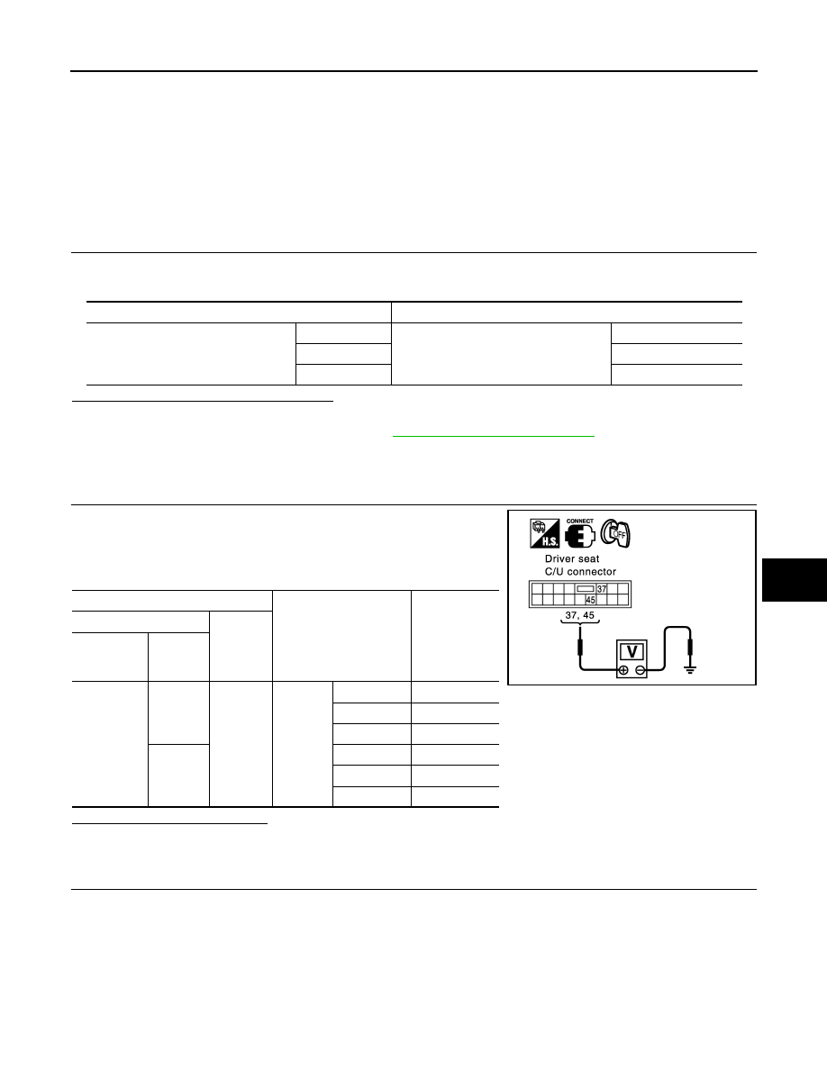
Check voltage between driver seat control unit harness connec-
tor and ground.
Is the inspection result normal?
YES
>> Replace lifting motor (front). (Built in seat slide cushion frame.)
NO
>> GO TO 2
2.
CHECK LIFTING MOTOR (FRONT) CIRCUIT
Test Item
Description
SEAT LIFTER FR
OFF
Seat lifting (front)
Stop
UP
Upward
DWN
Downward
Terminal
Test Item
Voltage (V)
(Approx.)
(+)
(-)
Driver seat
control unit
connector
Terminal
B203
37
Ground
SEAT
LIFTER
FR
OFF
0
UP
0
DWN (down)
Battery voltage
45
OFF
0
UP
Battery voltage
DWN (down)
0
PIIA4805E