Nissan Pathfinder (2008 year). Manual - part 11


  Index      Manuals     Nissan Pathfinder (2008 year) - Service and Repair Manual


Search            copyright infringement  


Content      ..     9      10      11      12     ..


Nissan Pathfinder (2008 year). Manual - part 11


MIRROR SENSOR

ADP-75

< COMPONENT DIAGNOSIS >

C

D

E

F

G

H

I

K

L

M

A

B

ADP

N

O

P

MIRROR SENSOR

DRIVER SIDE

DRIVER SIDE : Description

INFOID:0000000001711068

• The mirror sensor LH is installed to the door mirror LH.
• The resistance of 2 sensors (horizontal and vertical) is changed when the door mirror LH is operated.
• Automatic drive positioner control unit calculates the door mirror position according to the change of the volt-

age of 2 sensor input terminals.

DRIVER SIDE : Component Function Check

INFOID:0000000001711069

1.

 CHECK FUNCTION

1.

Select “MIR/SEN LH U-D”, “MIR/SEN LH R-L” in “Data monitor” with CONSULT-III.

2.

Check mirror sensor (driver side) signal under the following condition.

Is the indication normal?

YES

>> INSPECTION END

NO

>> Perform diagnosis procedure. Refer to 

ADP-75, "DRIVER SIDE : Diagnosis Procedure"

.

DRIVER SIDE : Diagnosis Procedure

INFOID:0000000001711070

1.

 CHECK DOOR MIRROR LH SENSOR SIGNAL

1.

Turn ignition switch ACC.

2.

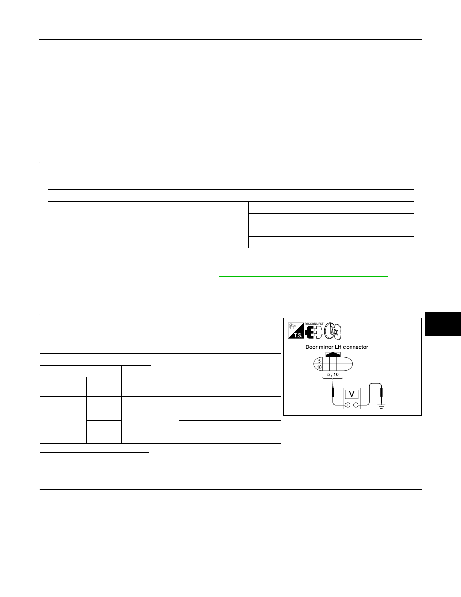
Check voltage between door mirror LH harness connector and
ground.

Is the inspection result normal?

YES

>> GO TO 5

NO

>> GO TO 2

2.

 CHECK DOOR MIRROR LH SENSOR CIRCUIT 1

Monitor item

Condition

Value

MIR/SEN LH U-D

Door mirror LH

Close to peak

3.4V

Close to valley

0.6V

MIR/SEN LH R-L

Close to right edge

3.4V

Close to left edge

0.6V

Terminals

Condition

Voltage (V)

(Approx.)

(+)

(–)

Door mirror 

LH connector

Terminal

D4

10

Ground

Door 
mirror
LH

Close to peak

3.4

Close to valley

0.6

5

Close to right edge

3.4

Close to left edge

0.6

LIIA1766E

ADP-76

< COMPONENT DIAGNOSIS >

MIRROR SENSOR

1.

Turn ignition switch OFF.

2.

Disconnect automatic drive positioner control unit and door mir-
ror LH connector.

3.

Check continuity between automatic drive positioner control unit
harness connector and door mirror LH harness connector.

4.

Check continuity between automatic drive positioner control unit harness connector and ground.

Is the inspection result normal?

YES

>> GO TO 3

NO

>> Repair or replace harness.

3.

 CHECK DOOR MIRROR LH SENSOR CIRCUIT 2 

1.

Check continuity between automatic drive positioner control unit
harness connector and door mirror LH harness connector.

2.

Check continuity between automatic drive positioner control unit
harness connector and ground.

Is the inspection result normal?

YES

>> GO TO 4

NO

>> Repair or replace harness.

4.

 CHECK PEDAL ADJUSTING OPERATION

1.

Connect driver seat control unit connector and door mirror LH connector.

2.

Turn ignition switch ON.

3.

Check pedal adjusting operation with memory function.

Is the operation normal?

YES

>> Replace door mirror sensor. (Built in door mirror LH.)

NO

>> Replace automatic drive positioner control unit.

5.

 CHECK INTERMITTENT INCIDENT

Refer to 

GI-51, "Intermittent Incident"

.

Is the inspection result normal?

YES

>> Replace automatic drive positioner control unit.

NO

>> Repair or replace the malfunctioning part.

Automatic drive 

positioner control 

unit connector

Terminal

Door mirror LH 

connector

Terminal

Continuity

M33

6

D4

10

Yes

22

5

Automatic drive positioner

 control unit connector

Terminal

Ground

Continuity 

M33

6

No

22

LIIA1768E

Automatic drive 

positioner control 

unit connector

Terminal

Door mirror LH 

connector

Terminal

Continuity

M34

33

D4

4

Yes

41

9

Automatic drive positioner

 control unit connector

Terminal

Ground

Continuity 

M34

33

No

41

LIIA1767E

MIRROR SENSOR

ADP-77

< COMPONENT DIAGNOSIS >

C

D

E

F

G

H

I

K

L

M

A

B

ADP

N

O

P

PASSENGER SIDE

PASSENGER SIDE : Description

INFOID:0000000001711071

• The mirror sensor RH is installed to the door mirror RH.
• The resistance of 2 sensors (horizontal and vertical) is changed when the door mirror RH is operated.
• Automatic drive positioner control unit calculates the door mirror position according to the change of the volt-

age of 2 sensor input terminals.

PASSENGER SIDE : Component Function Check

INFOID:0000000001711072

1.

CHECK FUNCTION

1.

Select “MIR/SEN RH U-D”, “MIR/SEN RH R-L” in “Data monitor” with CONSULT-III.

2.

Check the mirror sensor RH signal under the following conditions.

Is the indication normal?

YES

>> INSPECTION END

NO

>> Perform diagnosis procedure. Refer to 

ADP-77, "PASSENGER SIDE : Diagnosis Procedure"

.

PASSENGER SIDE : Diagnosis Procedure

INFOID:0000000001711073

1.

 CHECK DOOR MIRROR RH SENSOR SIGNAL

1.

Turn ignition switch ACC.

2.

Check voltage between door mirror RH harness connector and
ground.

Is the inspection result normal?

YES

>> GO TO 5

NO

>> GO TO 2

2.

 CHECK DOOR MIRROR RH SENSOR HARNESS CONTINUITY

Monitor item

Condition

Value

MIR/SEN RH U-D

Door mirror RH

Close to peak

3.4V

Close to valley

0.6V

MIR/SEN RH R-L

Close to right edge

3.4V

Close to left edge

0.6V

Terminals

Condition

Voltage (V)

(Approx.)

(+)

(–)

Door mirror 

RH con-

nector

Terminal

D107

10

Ground

Door mirror 
RH

Close to peak

3.4

Close to valley

0.6

5

Close to right edge

3.4

Close to left edge

0.6

LIIA1769E

ADP-78

< COMPONENT DIAGNOSIS >

MIRROR SENSOR

1.

Turn ignition switch OFF.

2.

Disconnect automatic drive positioner control unit and door mir-
ror RH.

3.

Check continuity between automatic drive positioner control unit
harness connector and door mirror RH harness connector.

4.

Check continuity between automatic drive positioner control unit harness connector and ground.

Is the inspection result normal?

YES

>> GO TO 3

NO

>> Repair or replace harness.

3.

CHECK DOOR MIRROR RH SENSOR POWER SUPPLY CIRCUIT 

1.

Check continuity between automatic drive positioner control unit
harness connector and door mirror RH harness connector.

2.

Check continuity between automatic drive positioner control unit
harness connector and ground.

Is the inspection result normal?

YES

>> GO TO 4

NO

>> Repair or replace harness.

4.

CHECK PEDAL ADJUSTING OPERATION

1.

Connect driver seat control unit connector and door mirror RH connector.

2.

Turn ignition switch ON.

3.

Check pedal adjusting operation with memory function.

Is the operation normal?

YES

>> Replace door mirror sensor. (Built in door mirror RH.)

NO

>> Replace automatic drive positioner control unit.

5.

CHECK INTERMITTENT INCIDENT

Refer to 

GI-51, "Intermittent Incident"

.

Is the inspection result normal?

YES

>> Replace automatic drive positioner control unit.

NO

>> Repair or replace the malfunctioning part.

Automatic drive posi-

tioner control unit 

connector

Terminal

Door mirror RH 

connector

Terminal

Continuity

M33

5

D107

10

Yes

21

5

Automatic drive positioner

 control unit connector

Terminal

Ground

Continuity 

M33

5

No

21

LIIA1772E

Automatic drive posi-

tioner control unit 

connector

Terminal

Door mirror RH 

connector

Terminal

Continuity

M34

33

D107

4

Yes

41

9

Automatic drive positioner

 control unit connector

Terminal

Ground

Continuity 

M34

33

No

41

LIIA1771E

SLIDING MOTOR

ADP-79

< COMPONENT DIAGNOSIS >

C

D

E

F

G

H

I

K

L

M

A

B

ADP

N

O

P

SLIDING MOTOR

Description

INFOID:0000000001711074

• The sliding motor LH is installed to the seat cushion frame.
• The sliding motor LH is installed with the driver seat control unit.
• The seat is slid forward/backward by changing the rotation direction of sliding motor LH.

Component Function Check

INFOID:0000000001711075

1.

 CHECK FUNCTION

1.

Select “SEAT SLIDE” in “Active test” mode with CONSULT-III.

2.

Check the sliding motor LH operation.

Is the operation of relevant parts normal?

YES

>> INSPECTION END

NO

>> Perform diagnosis procedure. Refer to 

ADP-79, "Diagnosis Procedure"

.

Diagnosis Procedure

INFOID:0000000001711076

1.

 CHECK SLIDING MOTOR LH POWER SUPPLY

1.

Turn the ignition switch ACC.

2.

Perform “Active test” (“SEAT SLIDE”) with CONSULT-lll

3.

Check voltage between driver seat control unit harness connec-
tor and ground.

Is the inspection result normal?

YES

>> Replace sliding motor LH. (Built in seat slide cushion frame.)

NO

>> GO TO 2

2.

 CHECK SLIDING MOTOR LH CIRCUIT

Test Item

Description

SEAT SLIDE

OFF

Seat sliding

Stop

FR

Forward

RR

Backward

Terminal

Test Item

Voltage (V)

(Approx.)

(+)

(-)

Driver seat 
control unit 

connector

Terminal

B203

35

Ground

SEAT 
SLIDE

OFF

0

FR (forward)

Battery voltage

RR (backward)

0

42

OFF

0

FR (forward)

0

RR (backward)

Battery voltage

PIIA4801E

ADP-80

< COMPONENT DIAGNOSIS >

SLIDING MOTOR

1.

Turn ignition switch OFF.

2.

Disconnect driver seat control unit and sliding motor LH.

3.

Check continuity between driver seat control unit harness con-
nector and sliding motor LH harness connector.

4.

Check continuity between driver seat control unit harness con-
nector and ground.

Is the inspection result normal?

YES

>> GO TO 3

NO

>> Repair or replace harness.

3.

 CHECK INTERMITTENT INCIDENT

Refer to 

GI-51, "Intermittent Incident"

.

Is the inspection result normal?

YES

>> Replace driver seat control unit.

NO

>> Repair or replace the malfunctioning part.

Driver seat control 

unit connector

Terminal

Sliding motor LH 

connector

Terminal

Continuity

B203

35

B204

6

Yes

42

4

Driver seat control 

unit connector

Terminal

Ground

Continuity 

B203

35

No

42

LIIA0696E

RECLINING MOTOR

ADP-81

< COMPONENT DIAGNOSIS >

C

D

E

F

G

H

I

K

L

M

A

B

ADP

N

O

P

RECLINING MOTOR

Description

INFOID:0000000001711077

• The reclining motor LH is installed to the seat back frame. 
• The reclining motor LH is activated with the driver seat control unit. 
• The seatback is reclined forward/backward by changing the rotation direction of reclining motor LH.

Component Function Check

INFOID:0000000001711078

1.

 CHECK FUNCTION

1.

Select “SEAT RECLINING” in “Active test” mode with CONSULT-III.

2.

Check the reclining motor LH operation.

Is the operation of relevant parts normal?

YES

>> INSPECTION END

NO

>> Perform diagnosis procedure. Refer to 

ADP-81, "Diagnosis Procedure"

.

Diagnosis Procedure

INFOID:0000000001711079

1.

 CHECK RECLINING MOTOR LH POWER SUPPLY

1.

Turn the ignition switch ACC.

2.

Perform “Active test” (“SEAT RECLINING”) with CONSULT-lll

3.

Check voltage between driver seat control unit harness connec-
tor and ground.

Is the inspection result normal?

YES

>> Replace reclining motor LH. (Built in seat back frame.)

NO

>> GO TO 2

2.

 CHECK RECLINING MOTOR LH CIRCUIT

Test Item

Description

SEAT RECLINING

OFF

Seat reclining

Stop

FR

Forward

RR

Backward

Terminal

Test Item

Voltage (V)

(Approx.)

(+)

(-)

Driver 

seat con-

trol unit 

connector

Terminal

B203

36

Ground

SEAT RE-
CLINING

OFF

0

FR (forward)

Battery voltage

RR (backward)

0

44

OFF

0

FR (forward)

0

RR (backward)

Battery voltage

PIIA4802E

ADP-82

< COMPONENT DIAGNOSIS >

RECLINING MOTOR

1.

Turn ignition switch OFF.

2.

Disconnect driver seat control unit connector and recling motor
LH.

3.

Check continuity between driver seat control unit harness con-
nector and reclining motor harness connector.

4.

Check continuity between driver seat control unit harness con-
nector and ground.

Is the inspection result normal?

YES

>> GO TO 3

NO

>> Repair or replace harness.

3.

 CHECK INTERMITTENT INCIDENT

Refer to 

GI-51, "Intermittent Incident"

.

Is the inspection result normal?

YES

>> Replace driver seat control unit.

NO

>> Repair or replace the malfunctioning part.

Driver seat control 

unit connector

Terminal

Reclining motor LH 

connector

Terminal

Continuity

B203

36

B205

4

Yes

44

3

Driver seat control unit 

connector

Terminal

Ground

Continuity 

B203

36

No

44

LIIA0697E


Content      ..     9      10      11      12     ..