Qashqai J11. Brake control system - part 8
C1198 VACUUM SENSOR
BRC-113
< DTC/CIRCUIT DIAGNOSIS >
[WITH ESP]
C
D
E
G
H
I
J
K
L
M
A
B
BRC
N
O
P
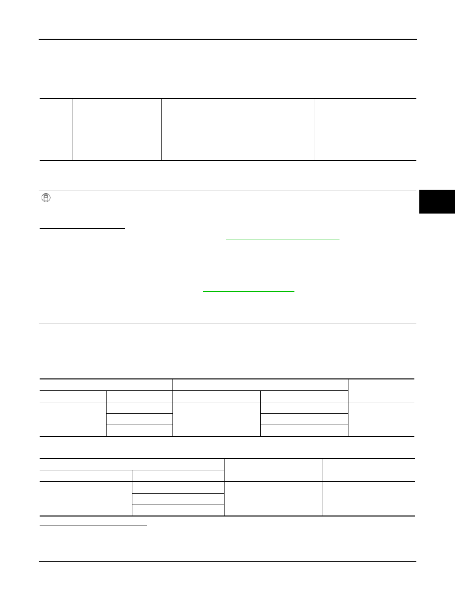
C1198 VACUUM SENSOR
DTC Logic
INFOID:0000000010329852
DTC DETECTION LOGIC
DTC CONFIRMATION PROCEDURE
1.
CHECK SELF-DIAGNOSTIC RESULT
With
CONSULT.
1.
Turn the ignition switch ON.
2.
Perform self-diagnostic result.
Is DTC C1198 detected?
YES
>> Proceed to diagnosis procedure. Refer to
BRC-113, "Diagnosis Procedure"
NO
>> Inspection End.
Diagnosis Procedure
INFOID:0000000010329853
Regarding Wiring Diagram information, refer to
1.
CHECK VACUUM SENSOR CIRCUIT
1.
Turn the ignition switch OFF.
2.
Disconnect vacuum sensor harness connector.
3.
Disconnect ABS actuator and electric unit (control unit) harness connector.
4.
Check continuity between vacuum sensor harness connector and ABS actuator and electric unit (control
unit) harness connector.
5.
Check continuity between vacuum sensor harness connector and ground.
Is the inspection result normal?
YES
>> GO TO 2.
NO
>> Repair or replace malfunctioning components.
2.
CHECK TERMINAL
DTC
Display Item
Malfunction detected condition
Possible causes
C1198
VACUUM SEN CIR
• When an open circuit is detected in vacuum sensor
circuit.
• When a short circuit is detected in vacuum sensor
circuit.
• When a malfunction is detected in vacuum sensor
noise.
• Harness or connector
• Vacuum sensor (brake booster)
• ABS actuator and electric unit
(control unit)
Vacuum sensor
ABS actuator and electric unit (control unit)
Continuity
Connector
Terminal
Connector
Terminal
E51
1
E18
12
Yes
2
24
3
5
Vacuum sensor
—
Continuity
Connector
Terminal
E51
1
Ground
No
2
3