Mitsubishi Lancer Evolution IX. Manual - part 283
 

  Index      Mitsubishi     Mitsubishi Lancer Evolution IX - service repair manual


Search            


Content   ..  281  282  283  284   ..


Mitsubishi Lancer Evolution IX. Manual - part 283


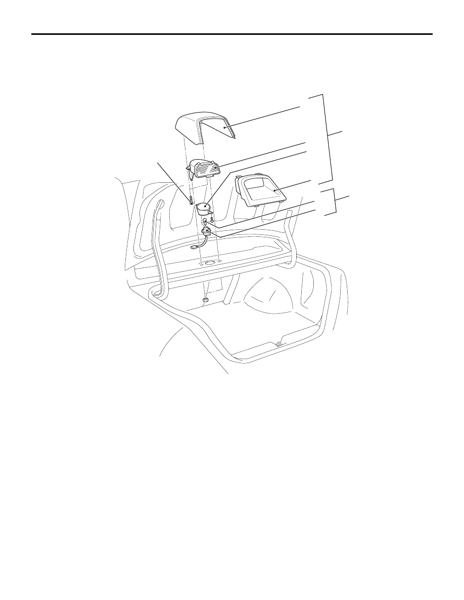
HIGH-MOUNTED STOP LAMP

CHASSIS ELECTRICAL

54A-69

HIGH-MOUNTED STOP LAMP

REMOVAL AND INSTALLATION

M1542005100526

AC305293AB

2

3

5

6

7

8

4

1

4.9 ± 0.7 N·m

<With rear shelf>

Removal steps 

1.

Socket assembly

2.

Socket 

3.

Bulb 

4.

High-mounted stop lamp assembly 

5.

Socket holder 

6.

High-mounted stop lamp cover 
(front) 

7.

High-mounted stop lamp cover 
(rear) 

8.

High-mounted stop lamp body 

Removal steps (Continued)

AC310882AB

1

2

<With rear spoiler>

Removal steps 

1.

Rear spoiler (Refer to GROUP 51, 
Rear spoiler 

P.51-16

).

<<

A

>>

2.

High-mounted stop lamp 

HIGH-MOUNTED STOP LAMP

CHASSIS ELECTRICAL

54A-70

REMOVAL SERVICE POINT
<<A>> HIGH-MOUNTED STOP LAMP 
REMOVAL <WITH REAR SPOILER>

AC005190

String

Connector

AC

Use the following steps to easily route high-mounted 
stop lamp harness in the event of installation:

CAUTION

Ensure that the string is tightly tied.
1. Tie a string on the high-mounted stop lamp 

harness (at the connector side).

2. Carefully pull out the high-mounted stop lamp.

LICENCE PLATE LAMP

CHASSIS ELECTRICAL

54A-71

LICENCE PLATE LAMP

REMOVAL AND INSTALLATION

M1542004200456

AC504380AB

3

4

2

1

Removal steps 

1.

Licence plate lamp lens

2.

Packing

3.

Socket

4.

Licence plate lamp bulb

HAZARD WARNING LAMP SWITCH

TROUBLESHOOTING

M1542000701333

FLASHER TIMER FUNCTION

The hazard warning lamps (flasher timer function) 
are controlled by the Smart Wiring System (SWS). 
For troubleshooting, refer to respective Groups 
below.

• Not using SWS monitor: GROUP 54B, SWS 

Troubleshooting 

P.54B-33

.

• Using SWS monitor: GROUP 54C, SWS Trouble-

shooting 

P.54C-20

.

SPECIAL TOOL

M1542000600935

Tool

Number

Name

Use

MB990784

MB990784

Ornament remover Removal of centre panel and 

centre air outlet panel

Removal steps (Continued)

HAZARD WARNING LAMP SWITCH

CHASSIS ELECTRICAL

54A-72

HAZARD WARNING LAMP SWITCH

REMOVAL AND INSTALLATION

M1542006600546

AC211605AC

3

4

2

1

5

Removal steps 

1. Knob
2. Centre panel

3. Meter bezel
4. Centre air outlet panel
5. Hazard warning lamp switch

INSPECTION

M1542011200920

HAZARD WARNING LAMP SWITCH CON-
TINUITY CHECK

AC305304

Switch position Tester 

connection

Specified 
condition

Released

− 2

Open circuit

Pressed

− 2

Less than 2 
ohms

Removal steps (Continued)


Content   ..  281  282  283  284   ..