Mitsubishi Lancer Evolution IX. Manual - part 282
 

  Index      Mitsubishi     Mitsubishi Lancer Evolution IX - service repair manual


Search            


Content   ..  280  281  282  283   ..


Mitsubishi Lancer Evolution IX. Manual - part 282


SIDE TURN-SIGNAL LAMP

CHASSIS ELECTRICAL

54A-65

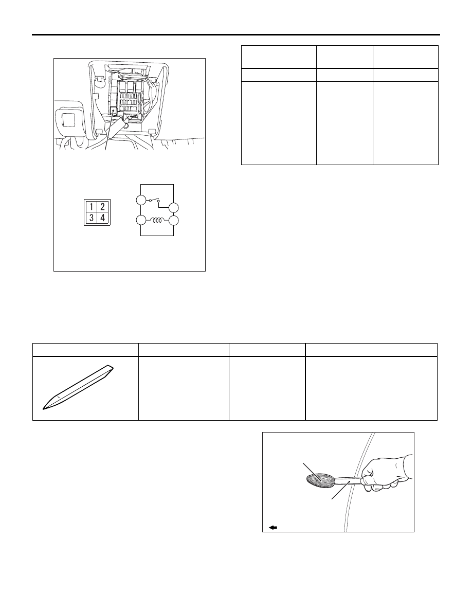
REAR FOG LAMP RELAY CHECK

AC305279

1

4

3

2

AB

Rear fog lamp relay

Battery voltage

Tester 
connection

Specified 
condition

Not supplied

− 4

Open circuit

• Connect 

terminal 3 to 
the positive 
battery terminal

• Connect 

terminal 2 to 
the negative 
battery terminal

− 4

Less than 2 
ohms

SIDE TURN-SIGNAL LAMP

SPECIAL TOOL

M1542000600913

Tool

Number

Name

Use

MB990784

MB990784

Ornament remover Removal of side turn-signal lamp

SIDE TURN-SIGNAL LAMP

REMOVAL AND INSTALLATION

M1542003300201

REMOVAL SERVICE POINT

AC005718

Side turn-signal lamps

MB990784

: Front of vehicle

AF

Use a special tool ornament remover (MB990784), 
etc. to remove the side turn-signal lamp by pushing 
the fender forward, bending the hook, and then 
unclamping the thumb.

ROOM LAMP

CHASSIS ELECTRICAL

54A-66

INSTALLATION SERVICE POINT

AC005719

Fender panel

Hook

Claw

Fender panel

: Front of vehicle

AE

Clamp the thumb on the fender panel the assemble 
the side turn-signal lamp.

ROOM LAMP

TROUBLESHOOTING

M1542000701634

DIMMER INTERIOR LAMP CONTROL 
FUNCTION

The room lamp off is delayed by ETACS-ECU. The 
lamps off delay time vary according to the conditions. 
The control details are as follows. The lamp delay off 
Yes/NO and delay time can be set with the settings 
(adjustment function). for adjustment methods and 
adjustment details (post-adjustment operations).

• ADJUSTMENT PROCEDURE

• Refer to GROUP 54B, SWS On-vehicle serv-

ice 

P.54B-302

.

• The room lamp lights up if the ignition switch is at 

the "LOCK" (OFF) position and either of the 
doors are opened (either of the door switches: 
ON). At this time, if all doors are closed (all door 
switches: OFF) then the lamp will gradually dim 
down to lamps off in about 15 seconds.

NOTE: When the lamps are dimmed and the ignition 

switch is turned ON or if the door is locked, then 
the dimming operations stop and the lamps are 
turned OFF.

• When the ignition switch is at the ON position and 

one of the doors are opened (one of the door 
switches: ON) then the room lamp will light up. At 
this time, if all doors are closed (all door switches: 
OFF) then the lamps will dim out.

• When the ignition key is pulled out the room lamp 

lights up and then will dim out in 15 seconds. The 
lamp will dim out if the ignition key is inserted 
again and the door is locked while the timer is 
activated.

The room lamp is controlled by the Smart Wiring 
System (SWS). For troubleshooting, refer to respec-
tive Groups below.

• Not using SWS monitor: GROUP 54B, SWS 

Troubleshooting 

P.54B-33

.

• Using SWS monitor: GROUP 54C, SWS Trouble-

shooting 

P.54C-20

.

INTERIOR LAMP AUTOMATIC 
SHUTDOWN FUNCTION

The interior lamp automatic shutdown function, dims 
out the room lamp and other interior lamps by acti-
vating the keep relay built-in the ETACS-ECU when 
the ignition switch is OFF and the multi-purpose fuse 
loaded signals built-in the ETACS-ECU is ON and 30 
minutes passes. The lamps lights back up if the igni-
tion switch is turned to the ON position or either of 
the doors is opened (either of the door switches: 
ON). The function Yes/No feature can be changed 
with the settings (adjustment function). for adjust-
ment methods and adjustment details (post-adjust-
ment operations).

• ADJUSTMENT PROCEDURE

• Refer to GROUP 54B, SWS On-vehicle serv-

ice

P.54B-302

.

The interior lamp are controlled by the Smart Wiring 
System (SWS). For troubleshooting, refer to respec-
tive Groups below.

• Not using SWS monitor: GROUP 54B, SWS 

Troubleshooting 

P.54B-33

.

• Using SWS monitor: GROUP 54C, SWS Trouble-

shooting 

P.54C-20

.

REAR COMBINATION LAMP

CHASSIS ELECTRICAL

54A-67

REAR COMBINATION LAMP

TROUBLESHOOTING

M1542000701322

The lamps setup on the rear combination lamp is 
controlled in the same manner as the lamps of the 
headlamp assembly. For details go to the reference. 
For troubleshooting, refer to respective Groups 
below.

• Not using SWS monitor: GROUP 54B, SWS 

Troubleshooting 

P.54B-33

.

• Using SWS monitor: GROUP 54C, SWS Trouble-

shooting 

P.54C-20

.

SPECIAL TOOL

M1542000600924

Tool

Number

Name

Use

MB990784

MB990784

Ornament remover Removal of rear combination 

lamp assembly

REAR COMBINATION LAMP

REMOVAL AND INSTALLATION

M1542003900537

AC310881

2

4

3

1

AB

4.9 ± 0.9 N·m

Removal steps 

1. Rear combination lamp assembly
2. Rear combination lamp body

3. Socket assembly
4. Bulb

Removal steps (Continued)

HIGH-MOUNTED STOP LAMP

CHASSIS ELECTRICAL

54A-68

HIGH-MOUNTED STOP LAMP

ON-VEHICLE SERVICE

HIGH-MOUNTED STOP LAMP BULB 
REPLACEMENT <WITH REAR SHELF>

M1542014600013

CAUTION

Do not touch bulb surface bare-handed or with 
dirty gloves. If dirt is attached on glass surface of 
the bulb, immediately use alcohol or thinner to 
remove dirt, and install the bulb after well dried.

AC305292AB

High-mounted
stop lamp

Remove socket from trunk compartment, and 
replace bulb.


Content   ..  280  281  282  283   ..