Mitsubishi Eclipse. Technical Information Manual (1994) - part 36


  Index      Mitsubishi     Mitsubishi Eclipse. Technical Information Manual (1994)


Search            


Content   ..  34  35  36  37   ..


Mitsubishi Eclipse. Technical Information Manual (1994) - part 36


POWER TRAIN 

 Manual Transaxle

Detent
ball (3)

Hub

Sleeve

 Stop ring Speed gear Sleeve 

stop ring

Gear
teeth

6

Spring

Gear cone

Sleeve
contacts
gear teeth

Full gear

engagement

Stop ring is pushed
into gear cone

045-050

Gear

0475-045

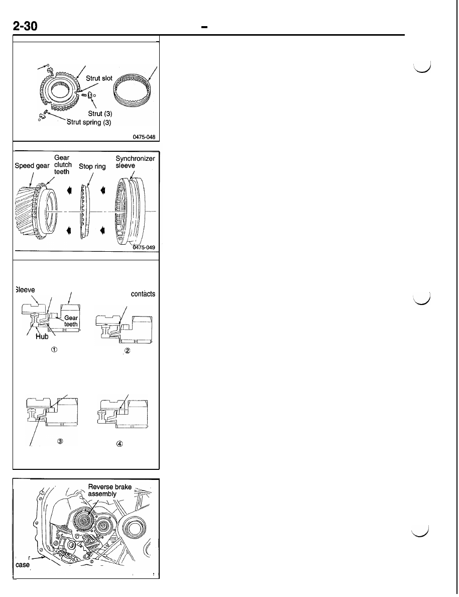
SYNCHRONIZER COMPONENTS
The synchronizer assemblies contain a sleeve, hub, struts,
springs and detent balls. The sleeve has inner splines that 
slide on the hub and an outer radial slot that engages the
shift fork. The hub has inner splines that engage the shafts
and outer splines that the sleeve rides on. The outer hub splines
have three slots, cut lengthwise, for the struts.

Stop rings are located between the synchronizer and the speed
gears. The stop ring acts as a clutch to bring both the shaft
and speed gear to the same speed, without gear clash. During
a shift, the sleeve slides on the hub and over the stop ring
to engage the gear clutch teeth. When the sleeve and the
stop ring touch, they immediately begin to equalize speeds,
or synchronize.

The balls are held against the sleeve by the synchronizer
springs. The struts slide in the hub slots during a shift. The
synchronizer springs use a detent ball to center the strut in
the synchronizer sleeve. Before the sleeve and stop ring contact
each other, the struts engage lugs on the stop ring, pushing
the stop ring onto the gear cone. The sleeve teeth then block
against the stop ring teeth until the gears synchronize. The
slots in the hub are slightly larger than the lugs on the stop

ring allowing the ring to turn when it contacts the gear. The

turning of the stop ring is often referred to as “clocking.”

REVERSE BRAKE

A reverse brake assembly is used to stop input shaft rotation
through a friction cone which is locked to the transaxle case.
The brake is located in the rear case behind the input shaft
5-R synchronizer. The brake prevents the reverse idler gear
from clashing with the input and output shaft gears.

POWER TRAIN 

 Manual Transaxle

Stop 

ring cone

 FWD

0475-025

The assembly looks and functions much like a synchronizer.

It consists of a stop ring, friction cone, shim, needle bearing

and bearing race.

If a shift to reverse is attempted before the clutch completely

spins down (stops turning) the brake will stop the input shaft
before the idler gear engages any other gear. The friction cone

has lugs that fit into the case and holds the cone stationary.

The 5-R synchronizer sleeve engages with the stop ring.

Shift System

The shift system is the link between the driver and the transaxle.
The shifter assembly selects different gears by moving the
shift forks. The shift system consists of the shift knob, lever,
selector cable, crossover cable and transaxle shift levers.

Two transaxle shift shafts operate the shift selector assembly

inside the transaxle. A selector shaft and a crossover shaft
move the shift assembly during shifts. The selector shaft con-

trols shifts into first and second, third and fourth, fifth and

reverse. The arrows indicate selector shaft movement.

The crossover shaft is used to move the shift assembly from
one plane to another. The crossover shaft moves the shift
assembly from side to side allowing for shifts between second
and third, fourth and fifth. A bias spring is located around the
crossover shaft. The bias spring returns the assembly to the
3-4 neutral position when the transaxle is in neutral and the
shift lever is released.

POWER TRAIN   Manual Transaxle

Selector
housing


‘5-032


0475-033

1 st speed

l-2 shift

fork

2nd speed

SHIFT SELECTOR ASSEMBLY
The shift selector assembly moves the appropriate shift fork
based on the drivers selection. The assembly consists of the
selector, shaft, housing, and pin.

The selector housing blocks the other shift forks and prevents
a shift into two gears at the same time. The selector pivots

in an arc to select the different shift forks.

A shift from fifth-to-reverse is blocked by a 5-R guide (guides
from 5th to 4th). The shift assembly has a pin sticking out
of one side that engages the guide as it comes out of fifth
gear. The guide pushes the pin and shift assembly away from

reverse gear.

SHIFT RAILS AND FORKS
The 

 uses three rail and fork assemblies. All of the

shift forks have dual functions in that they control shifts into
two different gears.

When the 1-2 shift fork moves to the front of the transaxle,
first gear is obtained. When it moves to the rear of the transaxle,
second gear is obtained.

POWER  TRAIN

 - Manual Transaxle

2-33

5th speed

SI

0475036

e

When the 3-4 shift fork moves to the front of the  transaxle,
third gear is obtained. When it moves to the rear of the transaxle,
fourth gear is obtained.

When the 5-R shift fork moves to the front of the transaxle,
fifth gear is obtained. When the 5-R shift fork and the reverse
shift fork move to the rear of the transaxle, reverse gear is
obtained.


Content   ..  34  35  36  37   ..