Mitsubishi Eclipse. Technical Information Manual (1994) - part 35
 

  Index      Mitsubishi     Mitsubishi Eclipse. Technical Information Manual (1994)


Search            


Content   ..  33  34  35  36   ..


Mitsubishi Eclipse. Technical Information Manual (1994) - part 35


POWER TRAIN   Manual Transaxle

Reverse idler

Input 

4

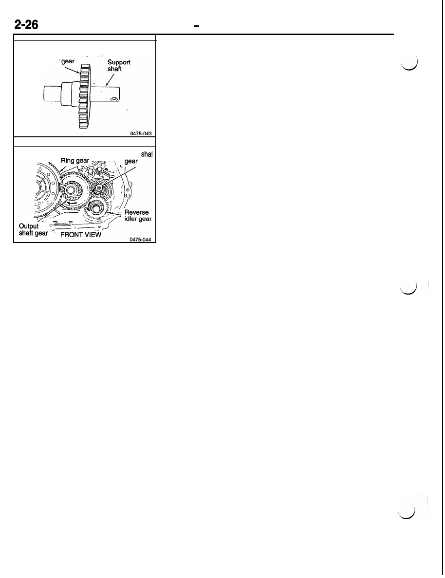
Reverse Idler Gear

The reverse idler gear slides into mesh with the input shaft

reverse gear and the gear teeth around the 1-2 synchronizer

sleeve. The idler gear allows the output shaft to turn in the
opposite direction for reverse operation. The gear is supported
by a shaft that is held in the front and rear cases.

POWER TRAIN 

 Manual Transaxle

DIFFERENTIAL ASSEMBLY

The differential assembly is supported by two ta-

pered roller bearings, one in the front case housing
and the other in the rear case housing.

Front tapered
roller bearing

roller bearing

Differential
assembly

POWER TRAIN 

 Manual Transaxle

0475-051

Roll

Differential case

Side gear thrust

thrust washer

Pinion shaft

0475-053

Differential

The 

 differential assembly is similar to previous 

axles, except the vehicle speed sensor drive gear is mounted
on the differential case. The ring gear is an open center design
and is bolted to the differential case. The pinion gear of the
output shaft is in constant mesh with the ring gear which pro-
vides torque to the differential.

The differential case transfers torque from the ring gear to
the differential side gears. The differential case is mounted

between the front and rear case housings and supported by

two tapered roller bearings. The outer bearing races are pressed

into the front and rear transaxle case housings. The outer
race mounted in the front transaxle case uses a selectable

shim behind it for differential bearing preload adjustment.

The differential allows the wheels to turn at different speeds
while the same amount of torque is applied to both. The differen-
tial contains two sets of gears, the pinion gears and the side

gears. The pinions are meshed with the side gears and turn
on the pinion shaft which is held in the case by a roll pin.

The side gears are splined to the halfshafts and transfer torque
to the wheels. The side gear clearance must be adjusted by

using selectable side gear thrust washers.

3-4 synchronizer

5-R synchronizer

Input shaft

POWER TRAIN 

 Manual Transaxle

2-29

Synchronizer

Three synchronizer assemblies are used in the

1-2 synchronizer is mounted on the output shaft

 transaxle. The 3-4 and 5-R synchronizers

assembly.

are mounted on the input shaft assembly and the

 shaft

I

l-2 synchronizer


Content   ..  33  34  35  36   ..