Mazda Engine SKYACTIV-G 2.5. Manual - part 17


  Index      Mazda     Mazda Engine SKYACTIV-G 2.5 - service manual 2012 year


Search            


Content   ..  15  16  17  18   ..


Mazda Engine SKYACTIV-G 2.5. Manual - part 17


MECHANICAL 

01-10–52

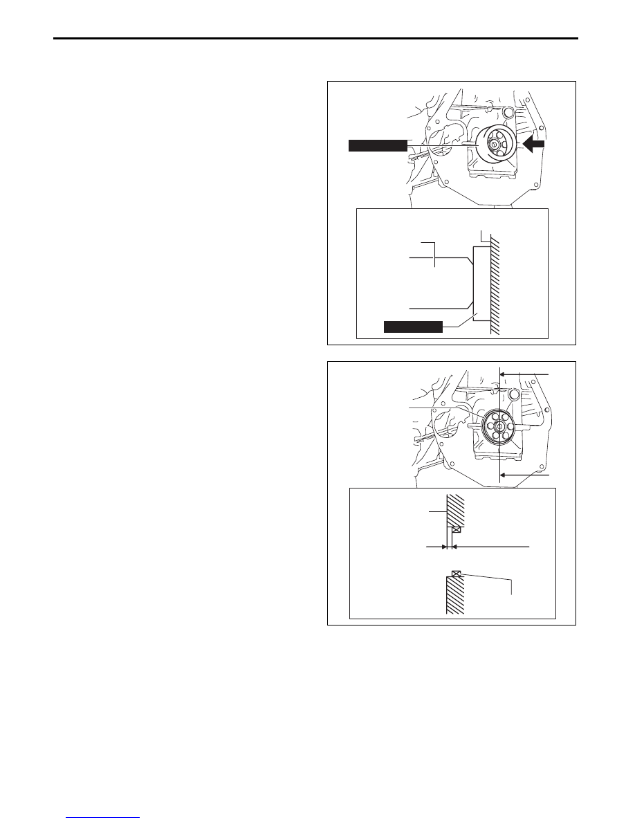
Rear Oil Seal Assembly Note

1. Apply clean engine oil to the inner surface of a new rear oil seal.

2. Insert the rear oil seal into the cylinder block by hand.

3. Tap the oil seal in evenly using the 

SST and a 

hammer.

Rear oil seal press on amount

0—0.5 mm {0—0.019 in}

A

HAMMER

CYLINDER BLOCK

VIEW FROM A

49 S033 101

49 S033 101

bpe1ze00000056

B

B

SECTION B-B

REAR OIL SEAL

REAR OIL SEAL

CYLINDER BLOCK

0—0.5 mm 
{0—0.019 in}

bpe5ue00000006

MECHANICAL 

01-10–53

01-10

End Plate Assembly Note

1. After end plate assembly, crimp the parts A and B shown in the figure.

Crimp procedure

Crimp depth: 0.1—1.0 mm {0.004—0.039 in}

Crimp width: 0.5—10.0 mm {0.02—0.39 in}

Crimp locations: Part A is 1 or more on one-side within shaded area and part B is 2 or more within 

shaded areas

2. After crimping, verify that there is no damage and removal of the end plate.

Dual-mass Flywheel (MTX)/ Drive Plate (ATX) Installation Bolt Assembly Note

Dual-mass flywheel installation bolt (MTX)

1. Hold the crankshaft using the 

SST (49 E011 1A0).

2. Temporarily tighten the new bolts.

Note

• If the dual-mass flywheel (secondary flywheel side) is not positioned properly, perform the following 

procedure to install it:

(1) Temporarily tighten the new bolts to the 

position as shown in the figure.

B

TUBULAR PIN

mm {in}

END PLATE

A

10 {0.39}

10 {0.39}

45

°

45

°

45

°

45

°

TUBULAR 
PIN

10 {0.39}

bpe2ue00000055

49 G033 102

49 E011 1A0

am6zzw00011777

MECHANICAL 

01-10–54

(2) Install the 

SST (49 S120 710) to the dual-

mass flywheel.

(3) Rotate the dual-mass flywheel (secondary 

flywheel side) using the 

SST (49 S120 710)

and then temporarily tighten the remaining 

new bolt after removing the 

SST (49 G033 

102).

3. Tighten the new bolts in two or three passes in 

the order shown in the figure.

Tightening torque

152—160 N·m {15.5—16.3 kgf·m, 113—118 

ft·lbf}

Drive plate installation bolt (ATX)

1. Hold the crankshaft using the 

SST.

2. Tighten the new bolts in two or three passes in 

the order shown in the figure.

Tightening torque

108—116 N·m {11.1—11.8 kgf·m, 80—85 

ft·lbf}

Knock Sensor (KS) Assembly Note

• Verify that there is no foreign matter caught between the KS unit and cylinder block.

• The direction of the knock sensor connector must 

be within the range shown in the figure.

End Of Sie

49 E011 1A0

49 S120 710

49 G033 102

am6xuw00005541

8

4

1

6

2

7

5

3

49 E011 1A0

ac5wzw00005664

49 E011 1A0

5

4

3

6

1

2

bpe1ze00000093

60º

KS

am6zzw00008568

MECHANICAL 

01-10–55

01-10

CYLINDER HEAD ASSEMBLY (I)

id011000504300

1. Assemble in the order indicated in the table.

.

3

1

2

R

R

7

SST

SST

5

4

6

9

8

OIL

OIL

N·m {kgf·cm, in·lbf}

8—11 
{82—112, 
71—97}

bpe1ze00000017

1

Lower valve spring seat

2

Valve seal

(See 01-10-56 Valve Seal Assembly Note.)

3

Valve

4

Valve spring

(See 01-10-56 Valve Spring Assembly Note.)

5

Upper valve spring seat

6

Valve keeper

(See 01-10-57 Valve Keeper Assembly Note.)

7

Water outlet

(See 01-10-57 Water Outlet Assembly Note.)

8

Thermostat

(See 01-10-58 Thermostat Assembly Note.)

9

Thermostat cover


Content   ..  15  16  17  18   ..