Mazda Engine SKYACTIV-G 2.5. Manual - part 15
 

  Index      Mazda     Mazda Engine SKYACTIV-G 2.5 - service manual 2012 year


Search            


Content   ..  13  14  15  16   ..


Mazda Engine SKYACTIV-G 2.5. Manual - part 15


MECHANICAL 

01-10–44

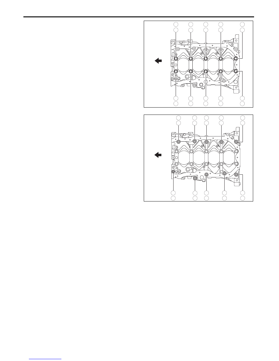
(2) Tighten lower cylinder block installation bolts 

A in the order shown in the figure using the 

following procedure:

Tightening procedure

Step 1: 38—42 N·m {3.9—4.2 kgf·m, 29—30 

ft·lbf}

Step 2: Loosen all the bolts (until bolts are 

torque-free).

Step 3: 30—34 N·m {3.1—3.4 kgf·m, 23—25 

ft·lbf}

Step 4: 57.5—62.5°

(3) Tighten the lower cylinder block installation 

bolts B in the order shown in the figure.

Tightening torque

19—25 N·m {2.0—2.5 kgf·m, 15—18 ft·lbf}

6. After verifying that silicone sealant protrudes to 

the rear oil seal press-in part, wipe away the 

excess silicone sealant.

• If silicone sealant does not protrude to the 

rear oil seal press-in part, remove the lower 

cylinder block and apply silicone sealant 

again.

Piston Pin Assembly Note

1. Apply clean engine oil to the piston pin.

2. Insert the piston pin to the piston and connecting rod.

Note

• When assembling the piston to the connecting rod, each one can be assembled in either direction.

Snap Ring Assembly Note

Caution

• Do not compress the outer diameter of the snap ring more than necessary when assembling the 

snap ring (20.66 mm {0.8134 in} or less).

1. Insert a new snap ring using a thin plier.

3

7

10

6

2

4

8

9

5

1

ENGINE 
FRONT

A

A

A

A

A

A

A

A

A

A

bpe2ue00000041

8

9

5

1

3

7

10

6

2

4

B

B

B

B

B

B

B

B

B

B

ENGINE 
FRONT

bpe2ue00000042

MECHANICAL 

01-10–45

01-10

Piston Ring Assembly Note

Note

• It is not required to position the end gap between the top ring and second ring.

1. Assemble the oil ring so that the end gap of each 

oil ring rail does not overlap as shown in the 

figure.

2. Assemble so that the identification paint marks on 

the top and second rings are visible to the right 

side of each end gap.

Note

• If there are no identification paint marks on 

the top and second rings, place the ring with 

the bigger inner circumference at the top as 

shown in the figure. 

30

°

30

°

PISTON PIN AXIS

LOWER OIL RING RAIL

UPPER OIL RING RAIL

OIL RING SPACER

bpe2ue00000043

TOP RING

END GAP

IDENTIFICATION PAINT MARK

SECOND RING

bpe1ze00000047

TOP RING

NOTCH

NOTCH

SECOND RING

bpe2ue00000044

MECHANICAL 

01-10–46

Connecting Rod Bearing Assembly Note

Caution

• If a connecting rod bearing is reused, assemble it to the same position and in the direction as 

before removal to prevent engine damage due to seizure or burning of the bearing.

• To prevent engine damage due to seizure or burning of the bearing, apply engine oil to the sliding 

part when assembling.

1. Apply engine oil to the connecting rod bearings.

2. Align the positioning tab of the connecting rod 

bearing with the positioning groove of the 

connecting rod and connecting rod cap, and 

assemble the bearings.

Piston, Connecting Rod Assembly Note

1. Insert the piston into the cylinder with the mark on 

top of the piston facing the intake side.

INSTALLED

CONNECTING ROD 
BEARING

CONNECTING ROD CAP

TAB

GROOVE

bpe1ze00000048

6TN

G

2

ENGINE 
FRONT

EX

IN

MARKED

bpe2ue00000045

MECHANICAL 

01-10–47

01-10

Connecting Rod Cap Assembly Note

Caution

• When assembling the connecting rod caps, align the broken, rough faces of the connecting rods 

and connecting rod caps.

• If the following condition is met, replace the connecting rod cap bolts.

Length exceeds maximum 

specification

Standard connecting rod cap bolt length

43.7—44.3 mm {1.73—1.74 in}

Maximum connecting rod cap bolt length

45.0 mm {1.77 in}

1. Position so that the broken, rough faces of the 

connecting rods and connecting rod caps are 

aligned exactly, and assemble the connecting rod 

caps.

2. Tighten the connecting rod cap bolts in the 

following two steps.

Tightening procedure

Step 1: 26—32 N·m {2.7—3.2 kgf·m, 20—23 ft·lbf}

Step 2: 80—100°

Pilot Bearing Assembly Note

1. Install new pilot bearing to the specified position 

using the following tools.

Tool

Snap-on brand millimeter size bushing 

driver set (A160M) adapter A160M7 (20—

22 mm {0.79—0.86 in})

• Use the adapter with the 20 mm {0.79 in} 

side of the A160M7 (20—22 mm {0.79—

0.86 in}) facing the pilot bearing side.

Substitution tool

Outer diameter: 21 mm {0.83 in}

Inner diameter: 19 mm {0.75 in}

Standard pilot bearing position

Distance A of pilot bearing from crankshaft 

end: 1.5—2.5 mm {0.060—0.098 in}

End Of Sie

L

adejjw00001214

bpe2ue00000046

PILOT BEARING

A

CRANKSHAFT

bpe2ue00000047


Content   ..  13  14  15  16   ..