Mazda Engine SKYACTIV-G 2.5. Manual - part 14
 

  Index      Mazda     Mazda Engine SKYACTIV-G 2.5 - service manual 2012 year


Search            


Content   ..  12  13  14  15   ..


Mazda Engine SKYACTIV-G 2.5. Manual - part 14


MECHANICAL 

01-10–40

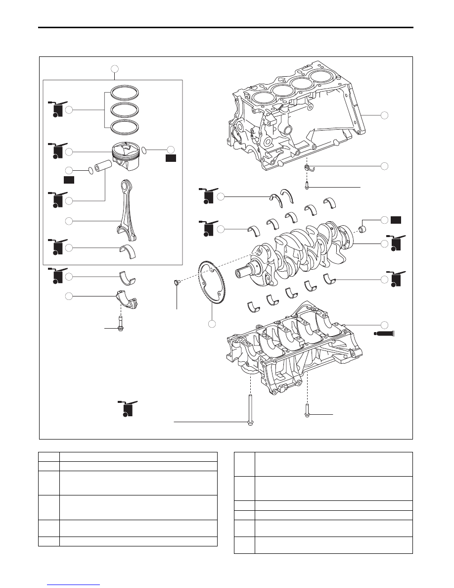
CYLINDER BLOCK ASSEMBLY (I)

id011000504000

1. Assemble in the order indicated in the table.

.

5

6

R

2

4

9

R

8

15

12

17

11

16

14

13

18

10

3

1

OIL

OIL

OIL

OIL

SEALANT

SEALANT

OIL

OIL

OIL

OIL

OIL

OIL

OIL

OIL

OIL

OIL

OIL

OIL

N·m {kgf·m, ft·lbf}

26—32 {2.7—3.2, 20—23}
+80—100

°

19—25 
{2.0—2.5, 
15—18}

20—26 
{2.1—2.6, 
15—19}

8—11 N·m 
{82—112 kgf·cm, 
71—97 in·lbf}

7

12

R

OIL

OIL

OIL

OIL

38—42 {3.9—4.2, 29—30}
LOOSEN ALL THE BOLTS (UNTIL 
BOLTS ARE TORQUE-FREE)
+30—34 {3.1—3.4, 23—25}
+57.5—62.5

°

bpe5ue00000004

1

Upper cylinder block

2

Oil jet valve

3

Thrust bearing

(See 01-10-41 Thrust Bearing And Main Bearing 

Assembly Note.)

4

Upper main bearing

(See 01-10-41 Thrust Bearing And Main Bearing 

Assembly Note.)

5

Plate

(See 01-10-42 Plate Assembly Note.)

6

Crankshaft

7

Lower main bearing

(See 01-10-41 Thrust Bearing And Main Bearing 

Assembly Note.)

8

Lower cylinder block

(See 01-10-42 Lower Cylinder Block Assembly 

Note.)

9

Connecting rod

10

Piston

11

Piston pin

(See 01-10-44 Piston Pin Assembly Note.)

12

Snap ring

(See 01-10-44 Snap Ring Assembly Note.)

MECHANICAL 

01-10–41

01-10

Thrust Bearing And Main Bearing Assembly Note

Caution

• If the thrust bearings and main bearings are reused, assemble the bearings to the same positions 

and in the direction as before removal to prevent engine damage due to seizure or burning of the 

bearing.

• To prevent engine damage due to seizure or burning of the bearing, apply engine oil to the sliding 

part when assembling.

Thrust bearing

1. Apply clean engine oil to the thrust bearings.

2. Assemble the bearings with the oil groove of the 

thrust bearing pointed toward the sliding surface.

Main bearing

1. Apply clean engine oil to the main bearings.

2. Align the positioning tab of the main bearing with 

the positioning groove of the lower and upper 

cylinder block, and assemble the bearings.

13

Piston ring

(See 01-10-45 Piston Ring Assembly Note.)

14

Upper connecting rod bearing

(See 01-10-46 Connecting Rod Bearing Assembly 

Note.)

15

Piston, connecting rod

(See 01-10-46 Piston, Connecting Rod Assembly 

Note.)

16

Lower connecting rod bearing

(See 01-10-46 Connecting Rod Bearing Assembly 

Note.)

17

Connecting rod cap

(See 01-10-47 Connecting Rod Cap Assembly 

Note.)

18

Pilot bearing (MTX)

(See 01-10-47 Pilot Bearing Assembly Note.)

THRUST BEARING

OIL GROOVE

bpe1ze00000043

MAIN BEARING

CYLINDER BLOCK

TAB

GROOVE

AFTER INSTALLATION

bpe1ze00000044

MECHANICAL 

01-10–42

Plate Assembly Note

Caution

• Placing the crankshaft on a disassembly bench will deform or damage it because the plate for the 

crankshaft position sensor signal detection installed to the crankshaft is larger than the 

counterweight. Therefore, set wood blocks or similar objects on the both sides of the crankshaft 

so that the plate does not contact the disassembly bench directly when placing the crankshaft on 

it bench.

1. Install the plate using the following procedure:

(1) Install the groove of the plate tooth to the 

position shown in the figure and temporarily 

tighten bolt A.

(2) Temporarily tighten the bolt B.

(3) Install bolt C and tighten the bolts to the 

specified tightening torque in the order of C, 

B, and A.

Tightening torque

20—26 N·m {2.1—2.6 kgf·m, 15—19 ft·lbf}

Lower Cylinder Block Assembly Note

1. Completely clean and remove any oil, dirt, sealant or other foreign matter that may be adhering to the lower 

cylinder block and cylinder block.

2. When reusing the lower cylinder block installation bolts, clean any old sealant from the bolts.

Caution

• Apply silicon sealant in a single, unbroken line.

• To prevent silicon sealant from hardening, adhere the engine front cover and the cylinder block 

firmly within 10 min. after applying silicon sealant. After adhering them, tighten the installation 

bolts immediately.

• Using bolts with the old seal adhering 

could cause cracks in the cylinder block.

GROOVE

PLATE

CRANKSHAFT

C

B

A

bpe2ue00000038

OLD SEALANT

DAMAGE

bpe2ue00000039

MECHANICAL 

01-10–43

01-10

3. Apply silicon sealant to the lower cylinder block shown in the figure.

Bead thickness

2—6 mm {0.1—0.2 in}

4. Install the lower cylinder block.

5. Tighten the lower cylinder block installation bolts using the following procedure:

(1) Apply clean engine oil to the seating surface and thread of lower cylinder block installation bolts A.

A

A

ENGINE FRONT

LOWER CYLINDER 
BLOCK

SEALANT

SEALANT

SEALANT

SEALANT

LESS THAN 
4 mm {0.2 in}

LESS THAN 
4 mm {0.2 in}

0.5—1.5 mm 
{0.02—0.05 in}

SEALANT

SEALANT

SECTION A-A

SEALANT

SEALANT

bpe1ze00000046


Content   ..  12  13  14  15   ..