Mazda Engine SKYACTIV-G 2.5. Manual - part 16


  Index      Mazda     Mazda Engine SKYACTIV-G 2.5 - service manual 2012 year


Search            


Content   ..  14  15  16  17   ..


Mazda Engine SKYACTIV-G 2.5. Manual - part 16


MECHANICAL 

01-10–48

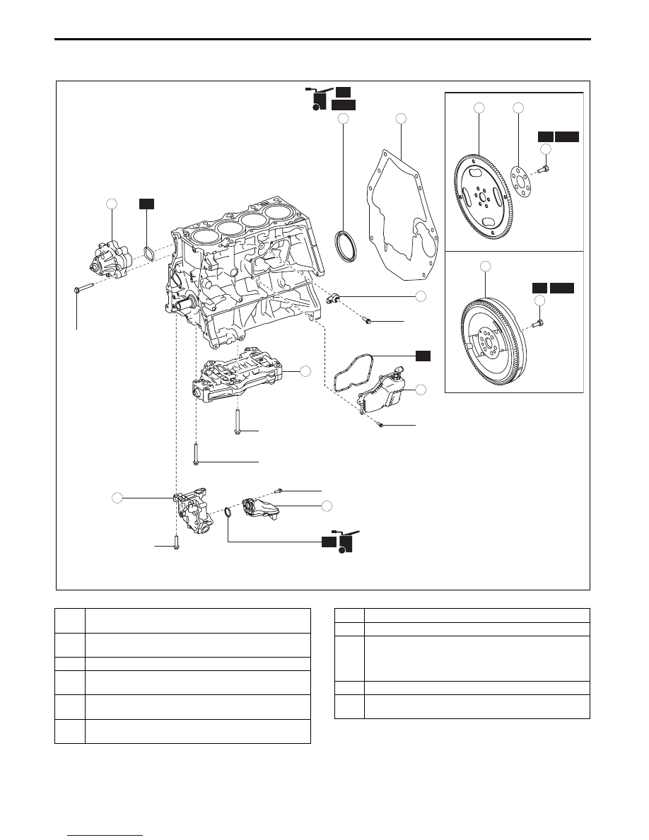
CYLINDER BLOCK ASSEMBLY (II)

id011000504100

1. Assemble in the order indicated in the table.

.

R

R

R

SST

4

2

3

R

OIL

OIL

N·m {kgf·m, ft·lbf}

108—116 
{11.1—11.8, 
80—85}

152—160 
{15.5—16.3, 
113—118}

17—23 
{1.8—2.3, 
13—16}

7

8

9

5

6

R

SST

OIL

OIL

1

*1: 8—11 N·m {82—112 kgf·m, 71—97 ft·lbf}

*1

*1

16—22 {1.7—2.2, 12—16}
+30—36 {3.1—3.6, 23—26}

20—26 {2.1—2.6, 15—19}

20—26 {2.1—2.6, 15—19}

20—26 {2.1—2.6, 15—19}

7

SST

9

R

ATX

MTX

10

11

bpe5ue00000005

1

Balancer unit

(See 01-10-49 Balancer Unit Assembly Note.)

2

Oil pump

(See 01-10-50 Oil Pump Assembly Note.)

3

Oil strainer

4

Water pump

(See 01-10-51 Water Pump Assembly Note.)

5

Rear oil seal

(See 01-10-52 Rear Oil Seal Assembly Note.)

6

End plate

(See 01-10-53 End Plate Assembly Note.)

7

Dual-mass flywheel (MTX), drive plate (ATX)

8

Backing plate (ATX)

9

Dual-mass flywheel (MTX)/ drive plate (ATX) 

installation bolt

(See 01-10-53 Dual-mass Flywheel (MTX)/ Drive 

Plate (ATX) Installation Bolt Assembly Note.)

10

Oil separator

11

Knock sensor (KS)

(See 01-10-54 Knock Sensor (KS) Assembly Note.)

MECHANICAL 

01-10–49

01-10

Balancer Unit Assembly Note

1. Assemble the balancer unit using the following procedure:

(1) Tighten the bolts in the order shown in the 

figure.

Tightening torque

(2) Retighten the bolts in the order of the 

numbers indicated in the figure.

Tightening torque

30—36 N·m {3.1—3.6 kgf·m, 23—26 ft·lbf}

4

3

1

2

BALANCER UNIT

ENGINE 
FRONT

5

6

bpe1ze00000051

Installation position

Tightening torque

1—4

16—22 N·m {1.7—2.2 kgf·m, 12—16 ft·lbf}

5, 6

20—26 N·m {2.1—2.6 kgf·m, 15—19 ft·lbf}

4

3

1

2

BALANCER UNIT

ENGINE 
FRONT

bpe1ze00000052

MECHANICAL 

01-10–50

Oil Pump Assembly Note

1. Install the oil pump using the following procedure:

(1) Temporarily tighten the 

three bolts shown in 

the figure.

(2) Tighten the 

two bolts shown in the figure to 

the specified torque.

Note

• The tightening order for the two bolts is 

optional.

Tightening torque

20—26 N·m {2.1—2.6 kgf·m, 15—19 ft·lbf}

(3) Finally, tighten the bolt shown in the figure to 

the specified torque.

Tightening torque

20—26 N·m {2.1—2.6 kgf·m, 15—19 ft·lbf}

OIL PUMP

BOLT

BOLT

BOLT

ENGINE FRONT

bpe1ze00000053

OIL PUMP

BOLT

BOLT

ENGINE FRONT

bpe1ze00000054

OIL PUMP

BOLT

ENGINE FRONT

bpe1ze00000055

MECHANICAL 

01-10–51

01-10

Water Pump Assembly Note

Caution

• Assemble the water pump gasket to the correct direction shown in the figure. Otherwise, it could 

leak engine coolant and damage the engine.

1. Insert a new water pump gasket into the water pump groove.

2. Install the water pump.

3. Tighten the bolts in the order shown in the figure.

Tightening torque

20—26 N·m {2.1—2.6 kgf·m, 15—19 ft·lbf}

WATER PUMP GASKET

GROOVE

WATER PUMP

bpe2ue00000053

WATER PUMP

1

3

2

bpe2ue00000054


Content   ..  14  15  16  17   ..