Lexus TX500H (2024 year). Manual in english - page 9
 

  Index      Manuals     Lexus TX500H (2024 year). Manual in english


Search            copyright infringement  


Content      ..     7      8      9      10     ..


Lexus TX500H (2024 year). Manual in english - page 9


280

4-5. Using the driving support systems

Vehicles with a head-up display

The function of each switch differs 
depending on the conditions and 
settings.

When a switch is touched, the function of 
each switch is displayed.

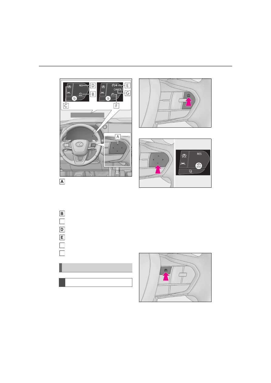
Driving assist mode select switch
Driving assist switch
“RES” switch
“+” switch
“-” switch
Cancel switch

1

Press the driving assist mode select 
switch to select cruise control.

The cruise control indicator will illuminate.

Vehicles without a head-up display

Vehicles with a head-up display

2

Using the accelerator pedal, accel-
erate to the desired vehicle speed 
(approximately 20 mph [30 km/h] 
or more), and press the driving 
assist switch to set the set vehicle 
speed.

The vehicle speed at the moment the 

switch is released will be the set vehicle 

speed.

Vehicles without a head-up display

Using the cruise control

Setting the vehicle speed

C

F

G

281

4-5. Using the driving support systems

4

Driving

Vehicles with a head-up display

Adjusting the set vehicle speed 
using the switches

To change the set vehicle speed, press the 
“+” switch or “-” switch until the desired 
speed is displayed.

Vehicles without a head-up display

1

Increase set vehicle speed

2

Decrease set vehicle speed

Vehicles with a head-up display

1

Increase set vehicle speed

2

Decrease set vehicle speed

The set vehicle speed will increase or 
decrease as follows:

Fine adjustment: By 1 mph (1.6 km/h) or 1 
km/h (0.6 mph) each time the switch is 
pressed
Large adjustment: Increases continuously 
while the switch is pressed and held

Increasing the set vehicle speed 
using the accelerator pedal

1

Depress the accelerator pedal to 
accelerate the vehicle to the 
desired vehicle speed.

2

Press the “+” switch.

Vehicles without a head-up display

Vehicles with a head-up display

1

Press the cancel switch or driving 
assist switch to cancel control.

Adjusting the set vehicle speed

Canceling/resuming control

282

4-5. Using the driving support systems

Control will also be canceled if the brake 

pedal is depressed.

2

Press the “RES” switch to resume 
control.

Automatic cancellation of the cruise 

control

In the following situations, the cruise control 

will be canceled automatically:

When the vehicle speed drops approxi-

mately 10 mph (16 km/h) or more below 

the set vehicle speed

When the vehicle speed drops below 

approximately 20 mph (30 km/h)

When the brake control or output restric-

tion control of a driving support system 

operates

(For example: PCS, drive-start control)

When the parking brake has been oper-

ated

Situations in which some or all of the 

functions of the system cannot operate: 

P.230

The operating state of cruise control is indicated.

Display and system operation state

Indicator

Multi-information display

Situation

White

Blank

Cruise control 

being OFF

283

4-5. Using the driving support systems

4

Driving

Green

Set vehicle 

speed: Green

Constant 

speed cruising

Green

Set vehicle 

speed: Green 
in reverse dis-

play

Set vehicle 

speed being 

exceeded

Indicator

Multi-information display

Situation

284

4-5. Using the driving support systems

Operation of this system is separated 
into 4 control states. Through control 
state “Warning phase 1” and “Warning 
phase 2”, the system determines if the 
driver is aware and responsive while 
outputting a warning and controlling 

Emergency Driving Stop 
System

The emergency driving stop system 
is a system which automatically 
decelerates and stops the vehicle 
within its lane if the driver becomes 
unable to continue driving the vehi-
cle, such as if they have suffered a 
medical emergency, etc.

During LTA (Lane Tracing Assist) 
control, if the system does not 
detect driving operations, such as if 
the driver is not holding the steer-
ing wheel, and determines the 
driver is not responsive, the vehicle 
will be decelerated and stopped 
within its current lane to help avoid 
a collision or reduce the impact of a 
collision.

The vehicle will also deceler-
ate/stop during the Traffic Jam 
Assist (if equipped) controls, when 
no driver’s response to the vehicle’s 
warning to hold the steering wheel 
is detected.

WARNING

For safe use

Driving safely is solely the responsibil-

ity of the driver. Pay careful attention to 

the surrounding conditions in order to 

ensure safe driving. The emergency 

driving stop system is designed to pro-

vide support in an emergency where it 

is difficult for the driver to continue 

driving, such as if they have had a med-

ical emergency. It is not designed to 

support driving while drowsy or in 

poor physical health, or inattentive 

driving.

Although the emergency driving stop 

system is designed to decelerate the 

vehicle within its lane to help avoid or 

help reduce the impact of a collision if 

the system determines that it is difficult 

for the driver to continue driving, its 

effectiveness may change according 

to various conditions. Therefore, it may 

not always be able to achieve the same 

level of performance. Also, if the oper-

ating conditions are not met, this func-

tion will not operate.

After the emergency driving stop sys-

tem operates, if driving becomes pos-

sible again, immediately begin driving 

again or, if necessary, park the vehicle 

on the shoulder of the road and set a 

warning reflector and flare to warn 

other drivers of your stopped vehicle.

After this system operates, passengers 

should attend to the driver as neces-

sary and take appropriate hazard pre-

vention measures, such as moving to a 

place where safety can be ensured, 

such as the shoulder of the road or 

behind a guardrail.

This system detects the condition of 

the driver through the operation of the 

steering wheel. This system may oper-

ate if the driver is aware but intention-

ally and continuously does not operate 

the vehicle. Also, the system may not 

operate if it cannot determine that the 

driver is not responsive, such as if they 

are leaning on the steering wheel.

Situations in which the driver monitor 

may not operate properly (vehicles 

with a driver monitor): 

P.232

Summary of the system

285

4-5. Using the driving support systems

4

Driving

the vehicle speed. If the system deter-
mines the driver is not responsive, it will 
operate in control state “Deceleration 
stop phase” and “Stop hold phase” and 
decelerate and stop the vehicle. It will 
then operate continuously in “Stop 
hold phase”.

Operating conditions

This system operates when all of the follow-

ing conditions are met:

When the LTA is on

Or during the Traffic Jam Assist controls (if 
equipped)

When the vehicle speed is approximately 

30 mph (50 km/h) or more

During the Traffic Jam Assist (if equipped) 
controls, the system may operate at below 
30 mph (50 km/h).

Operation cancelation conditions

In the following situations, system operation 

will be canceled:

When LTA control has been canceled 

(the LTA switch has been pressed, etc.)

When the dynamic radar cruise control 

has been canceled

When driver operations are detected 

(the steering wheel is held, the brake 

pedal, accelerator pedal, parking brake, 

hazard light switch, or turn signal lever is 

operated)

When the driving assist switch is pressed 

while in the stop and hold phase

When the power switch has been turned 

from ON to off

Situations in which some or all of the 

functions of the system cannot operate: 

P.230

LTA control when operation is canceled

When emergency driving stop system 

operation is canceled, LTA control may also 

be canceled.

If driving operations are not detected 
after the hands off steering wheel 
warning operates, a buzzer will sound 
intermittently and a message will be 
displayed to warn the driver, and the 
system will judge if the driver is respon-
sive or not. If driving operations, such 
as holding the steering wheel, are not 
performed within a certain amount of 
time, the system will enter warning 
phase 2.
Vehicles with a driver monitor camera: 
Depending on the type of detection of 
the driver’s unresponsiveness, the sys-
tem may skip warning phase 1 and start 
the control of warning phase 2.

After entering warning phase 2, a 
buzzer will sound in short intervals and 
a message will be displayed to warn the 
driver, and the vehicle will slowly decel-
erate. If driving operations, such as 
holding the steering wheel, are not 
performed within a certain amount of 
time, the system will determine that the 
driver is not responsive and enter the 
deceleration stop phase.

The audio system will be muted until the 
driver becomes responsive.
When the vehicle is decelerating, the 
brake lights may illuminate, depending on 
the road conditions, etc.

After entering the deceleration stop 

Warning phase 1

Warning phase 2

Deceleration stop phase

286

4-5. Using the driving support systems

phase, a buzzer will sound continu-
ously and a message will be displayed 
to warn the driver, and the vehicle will 
slowly decelerate and stop. After the 
vehicle stops, the system will enter the 
stop and hold phase.

After the vehicle is stopped, the park-
ing brake will be applied automatically. 
After entering the stop and hold phase, 
the buzzer will continue sounding con-
tinuously and the emergency flashers 
(hazard lights) will flash to warn other 
drivers of the emergency.

Restricted functions after the operation 

is canceled

After shifting to the deceleration stop 

phase, the following functions will not be 

available until the hybrid system is 

re-started even though the emergency driv-

ing stop system is canceled:

LTA

LCA (if equipped)

Traffic Jam Assist (if equipped)

*

: If equipped

Traffic Jam Assist is a system which, 
through confirmation of the conditions 
by the driver, provides lane keeping, 
accelerating/decelerating, stopping, 
and starting off support on some high-
ways and expressways. Also, in an 
emergency, the system can decelerate 
and stop, to help avoid a collision or 
help reduce the impact of a collision.

Sensors which detect the surround-
ing conditions (

P.225)

Sensors which detect the driver 
condition (

P.226)

Situations in which some or all of the 

functions of the system cannot operate

P.230

Changes in brake operation sound and 

pedal response

P.230

Situations in which the driver monitor 

may not operate properly

P.230

P.284

Stop hold phase

Traffic Jam Assist

*

Function Outline

Sensors that support the Traffic 
Jam Assist

Emergency Driving Stop System

287

4-5. Using the driving support systems

4

Driving

P.267

The Traffic Jam Assist function, through 
confirmation of the conditions by the 
driver, provides lane keeping, acceler-
ating/decelerating and stopping sup-
port on some highways and 
expressways.
This function is operable when all of the 
operation conditions are met.
When this function is operating, it is 
possible to take your hands off of the 
steering wheel. (

P.289)

Before using the Traffic Jam Assist function, 
familiarize yourself with the content of the 
dynamic radar cruise control and the LTA 
(Lane Tracing Assist).
Make sure that the driver steers the vehicle 
when entering a service area/parking area 
or toll gate, or when changing lanes.

When the operation of Traffic Jam 
Assist is started, the following message 
will be displayed:

“Allow Driver Monitor Camera 
Recording?”

When recording is approved, the system 
records images of the area around the 
driver in certain crash or near crash-like 
situations, such as an SRS airbag being 
deployed or the vehicle hitting an object on 
the road. (

P.9)

Extended resume time of 
Dynamic radar cruise control

Traffic Jam Assist Function

Driver monitor camera record-
ing

WARNING

For safe use

Driving safely is solely the responsibil-

ity of the driver. Do not overly rely on 

this system, and pay careful attention 

to the surrounding conditions in order 

to ensure safe driving.

The Traffic Jam Assist function is not an 

automated driving system.

This function provides the driver with 

information and driving assistance 

according to the road shape and con-

ditions, traffic conditions, and the con-

dition of the driver themself. Always 

pay careful attention to the surround-

ing conditions as use of the system is 

the responsibility of the driver.

Depending on the condition of the sur-

rounding area, the road, or the driver, 

the Traffic Jam Assist function may not 

operate or operation may be sus-

pended. Also, it may not always be 

able to achieve the same level of per-

formance. Read the operating condi-

tions of the function carefully. Do not 

overly rely on this function and always 

drive carefully.

As the recognition performance and 

control performance of the Traffic Jam 

Assist function are limited, driver oper-

ation is necessary to ensure safety 

while the system is operating. Also, the 

steering assist of this system is 

designed to operate only for slow 

steering operations during a traffic 

jam. While this function is operating, 

the lane deviation control function of 

the LDA will not operate. If, for some 

reason, the vehicle is about to deviate 

the lane, it is the driver’s responsibility 

to drive properly.

288

4-5. Using the driving support systems

WARNING

Even if Traffic Jam Assist is operating 

properly, the surrounding conditions 

as recognized by the driver and 

detected by the system may differ. 

Therefore, it is necessary for the driver 

to pay attention, assess risks, and 

ensure safety. Over-reliance on this 

system to drive the vehicle safely may 

lead to an accident resulting in death 

or serious injury.

While the Traffic Jam Assist function is 

operating, as driver operation may 

become necessary, the driver must 

ensure they have clear visibility of their 

surroundings.

In certain situations, a message urging 

the driver to hold the steering wheel 

may be displayed by the Traffic Jam 

Assist function. In this case, hold the 

steering wheel and drive the vehicle 

manually to ensure safety.

The Traffic Jam Assist function cannot 

detect the following objects. Operate 

the steering wheel, accelerator pedal, 

or brake pedal as necessary to avoid a 

collision. As the function will not be 

able to provide appropriate control, 

using it may lead to an accident result-

ing in death or serious injury.

• Objects on the road surface

• Vehicles outside of a lane (such as on 

the shoulder of the road)

• Potholes, cracks, ruts, or other road 

damage

• Road construction zones

• Vehicles running in parallel with your 

vehicle or nearby walls

• Animals

Situations in which Traffic Jam Assist 

Function should not be used

Do not use Traffic Jam Assist Function in 

situations such as the following. As the 

system will not be able to provide appro-

priate control, using it may lead to an 

accident resulting in death or serious 

injury.

When it is necessary to disable the sys-

tem

P.224

Situations in which the sensors may not 

operate properly

P.228

Situations in which the lane may not be 

detected

P.229

Situations in which the function may 

not operate properly

In situations such as the following, the 

Traffic Jam Assist function may not oper-

ate properly. Manually operate the vehi-

cle as necessary.

When a sensor is splashed by water

When the ambient temperature is high 

or low

When a vehicle cuts in front of your 

vehicle

When another lane merges into the 

lane in the same traveling direction as 

your vehicle

When driving in low visibility condition

When the vehicle posture is changing

When the traction on the road surface 

differs greatly between the left and 

right side tires

When driving on an expressway with 

no median strips or when driving on an 

expressway equipped with temporary 

median markers, such as poles.

289

4-5. Using the driving support systems

4

Driving

Operating conditions of the function

This function is operable when all of the fol-

lowing conditions are met:

The system detects lane lines and the 

path of preceding or surrounding vehi-

cles.

The dynamic radar cruise control and the 

lane tracing assist are operating.

The turn signal lever is not being oper-

ated.

The vehicle is not being driven around a 

sharp curve.

The vehicle is being driven in the center 

of a lane.

The driver monitor camera is detecting 

that the driver is facing front of the vehi-

cle.

The vehicle is driving in traffic jam on a 

highway or expressway at approximately 

25 mph (40 km/h) or less. (In some situ-

ations, such as when a traffic jam starts, 

this function may be operational at 

approximately 20 mph [30 km/h] or 

less.)

Safety Connect is being subscribed to.

The driver’s door is closed.

The driver’s seat belt is fastened.

Customized setting of the Traffic Jam 

Assist is not set to off.

Functions and components composing 

the system are in proper condition.

Customized setting of the PCS (Pre-Col-

lision System) is not set to off.

Customized setting of the dynamic radar 

cruise control (re-start time extension) is 

not set to off.

Temporary cancelation of the function

When the operating conditions are no 

longer met, a function may be temporar-

ily canceled. However, when the opera-

tion conditions are met again, operation 

of the function will automatically be 

restored.

If the operating conditions of a function 

are no longer met while the function is 

operating, a buzzer may sound with a dis-

play to indicate that the function has been 

temporarily canceled. If no driver’s 

responses to the indication are detected, 

the driver emergency stop assist function 

may operate. For types of display and 

action to be taken, see the page men-

tioned below. (

P.290)

Driving operations during controlled 

driving

Accelerator pedal

As with normal driving, acceleration can 
be performed by depressing the accelera-
tor pedal. In some situations, such as when 
driving at approximately 6 mph (10 km/h) 
or more and the accelerator pedal is 
depressed, this function will be canceled.

Brake pedal

As with normal driving, deceleration can 
be performed by depressing the brake 
pedal. However, controlled driving will be 
cancelled.

Steering wheel

As with normal driving, the steering wheel 
can be operated. If the steering wheel is 
operated more than a certain amount, con-
trolled driving will be cancelled.

WARNING

When there is a significant difference 

in speed between your vehicle and the 

other vehicle

The map data has not been updated 

properly.

To prevent malfunction of the radar 

sensors

P.226

To prevent malfunction of the front 

camera

P.227

Front camera installation area on the 

windshield

P.228

290

4-5. Using the driving support systems

When a warning message is displayed

“TrafficJamAsst System Malfunction Visit 

Your Dealer”

The Traffic Jam Assist function may not be 
operating properly.

“TrafficJamAsst Unavailable Stop Assist 

Activated”

The system temporarily cannot be used as 
the driver emergency stop assist function 
has operated.

The setting of Traffic Jam Assist can 
be enabled/disabled through a cus-
tomize setting. (

P.550)

The setting of driver monitor cam-
era recording can be enabled/dis-
abled through a customize setting. 
(

P.550)

The following displays indicate the operating status of the Traffic Jam Assist func-
tion:

Changing Traffic Jam Assist set-
tings

Displays and system operation

Display

Status

Action to be taken

Traffic Jam Assist function is 
operating

(Grey)

Traffic Jam Assist function is 
about to end

Hold the steering wheel.

(Orange)

Traffic Jam Assist function has 
ended

Hold the steering wheel.

(Red)

Operation of either or both of 
dynamic radar cruise control 
/LTA (Lane Tracing Assist) 
ended

Manually operate the steering 
wheel immediately.

291

4-5. Using the driving support systems

4

Driving

(Yellow)

Indicates that driving actions are 
necessary to cope with cut-in or 
other behavior of surrounding 
vehicles

The driver must operate the 
steering wheel, accelerator 
pedal and brake pedal in accor-
dance with the surrounding envi-
ronment.

Indicates that the recording 
function of the driver monitor 
camera is operational (Blinking 
of this icon indicates that record-
ing is undergoing, and constant 
illumination indicates ready for 
recording.)

Display

Status

Action to be taken

292

4-5. Using the driving support systems

Center display

Turning the Blind Spot Monitor on/off.

Outside rear view mirror indicators

When a vehicle is detected in a blind spot 
of the outside rear view mirrors or 
approaching rapidly from behind into a 
blind spot, the outside rear view mirror 
indicator (

P.74) on the detected side will 

illuminate. If the turn signal lever is oper-
ated toward the detected side, the outside 
rear view mirror indicator will flash and a 
buzzer will sound.

Driving assist information indicator

Illuminates when the Blind Spot Monitor is 
turned off. At this time, a message will be 
displayed on the multi-information display.

Outside rear view mirror indicator visi-

bility

In strong sunlight, the outside rear view mir-

ror indicator may be difficult to see.

Buzzer

If the volume setting of the audio system is 

high or the surrounding area is loud, it may 

be difficult to hear the buzzer.

Customization

Some functions can be customized. 

(

P.550)

BSM (Blind Spot Monitor)

The Blind Spot Monitor is a system 
that uses rear side radar sensors 
installed on the inner side of the 
rear bumper on the left and right 
side to assist the driver in confirm-
ing safety when changing lanes.

WARNING

Cautions regarding the use of the sys-

tem

The driver is solely responsible for safe 

driving. Always drive safely, taking 

care to observe your surroundings.

The Blind Spot Monitor is a supple-

mentary function which alerts the 

driver that a vehicle is in a blind spot of 

the outside rear view mirrors or is 

approaching rapidly from behind into a 

blind spot. Do not overly rely on the 

Blind Spot Monitor. As the function 

cannot judge if it is safe to change 

lanes, over reliance could lead to an 

accident resulting in death or serious 

injury.

As the system may not function cor-

rectly under certain conditions, the 

driver’s own visual confirmation of 

safety is necessary.

System components

WARNING

To ensure the system can operate 

properly

Blind Spot Monitor sensors are installed 

behind the left and right sides of the rear 

bumper respectively. Observe the fol-

lowing to ensure the Blind Spot Monitor 

can operate correctly.

C

293

4-5. Using the driving support systems

4

Driving

The Blind Spot Monitor can be 
enabled/disabled through a customize 
setting. (

P.550)

When the Blind Spot Monitor is off, the 
driving assist information indicator 
(

P.74) will illuminate and a message 

will be displayed on the multi-informa-
tion display.
Each time the power switch is turned to 
ON, the Blind Spot Monitor is enabled.

WARNING

Keep the sensors and the surrounding 

areas on the rear bumper clean at all 

times.

If a sensor or its surrounding area on the 
rear bumper is dirty or covered with 
snow, the Blind Spot Monitor may not 
operate and a warning message will be 
displayed. In this situation, clear off the 
dirt or snow and drive the vehicle with 
the operation conditions of the BSM 
function (

P.295) satisfied for approxi-

mately 10 minutes. If the warning mes-
sage does not disappear, have the 
vehicle inspected by your Lexus dealer.

Do not attach accessories, stickers 

(including transparent stickers), alumi-

num tape, etc. to a sensor or its sur-

rounding area on the rear bumper.

Do not paint the surrounding area of a 

sensor on the rear bumper.

Do not subject a sensor or its sur-

rounding area on the rear bumper to a 

strong impact.

If a sensor is moved even slightly off 

position, the system may malfunction 

and vehicles may not be detected cor-

rectly.

In the following situations, have your 

vehicle inspected by your Lexus 

dealer.

• A sensor or its surrounding area is 

subject to a strong impact.

• If the surrounding area of a sensor is 

scratched or dented, or part of them 

has become disconnected.

Do not disassemble the sensor.

Do not modify the sensor or surround-

ing area on the rear bumper.

If a sensor or the rear bumper needs to 

be removed/installed or replaced, 

contact your Lexus dealer.

The sensors are likely to be affected by 

paint on the rear bumper. If the rear 

bumper is not repaired correctly, the 

Blind Spot Monitor may not operate 

with a warning message displayed. If 

any paint repair is needed, contact 

your Lexus dealer.

Turning the Blind Spot Monitor 
on/off

294

4-5. Using the driving support systems

Objects that can be detected while driving

The Blind Spot Monitor uses rear side radar sensors to detect the following vehi-
cles traveling in adjacent lanes and advises the driver of the presence of such vehi-
cles via the indicators on the outside rear view mirrors.

Vehicles that are traveling in areas that are not visible using the outside rear 
view mirrors (the blind spots)
Vehicles that are approaching rapidly from behind in areas that are not visible 
using the outside rear view mirrors (the blind spots)

Detection range while driving

The areas that vehicles can be detected in are outlined below.

The range of each detection area is:

Approximately 1.6 ft. (0.5 m) to 11.5 ft. (3.5 m) from either side of the vehicle

*1

Approximately 3.3 ft. (1 m) forward of the rear bumper

*2

Approximately 9.8 ft. (3 m) from the rear bumper

Approximately 9.8 ft. (3 m) to 230 ft. (70 m) from the rear bumper

*3

*1

: The area between the side of the vehicle and 1.6 ft. (0.5 m) from the side of the vehicle 

cannot be detected.

*2

: While the vehicle is to being overtaken, up to approximately 9.8 ft. (3 m) forward of the 

Blind Spot Monitor operation

C

295

4-5. Using the driving support systems

4

Driving

rear bumper will be detected.

*3

: The greater the difference in speed between your vehicle and the detected vehicle is, 

the farther away the vehicle will be detected, causing the outside rear view mirror indi-
cator to illuminate or flash.

The Blind Spot Monitor linked 
function

The LDA (Lane Departure Alert) has a 
function that uses information of 
detected vehicles driving in an adja-
cent lane. For details about the function 
and its operating conditions, P.251.

The Blind Spot Monitor is operational 

when

The Blind Spot Monitor is operational when 

all of the following conditions are met:

The power switch is in ON.

The Blind Spot Monitor is on.

The shift position is in a position other 

than R.

The vehicle speed is greater than approx-

imately 7 mph (10 km/h).

The Blind Spot Monitor will detect a 

vehicle when

The Blind Spot Monitor will detect a vehicle 

present in the detection area in the follow-

ing situations:

A vehicle in an adjacent lane overtakes 

your vehicle.

You overtake a vehicle in an adjacent lane 

slowly.

Another vehicle enters the detection 

area when it changes lanes.

Situations in which the Blind Spot Moni-

tor cannot detect vehicles.

The Blind Spot Monitor cannot detect the 

following vehicles and other objects:

Small motorcycles, bicycles, pedestrians, 
etc.

*

Vehicles traveling in the opposite direc-

tion

Guardrails, walls, signs, parked vehicles 

and similar stationary objects

*

Following vehicles that are in the same 
lane

*

Vehicles traveling 2 lanes away from your 
vehicle

*

Vehicles which are being overtaken rap-
idly by your vehicle

*

*

: Depending on the conditions, detection 

of a vehicle and/or object may occur.

Conditions in which a buzzer may not 

sound

In situations such as the following, while the 

turn signal lever is being operated, the indi-

cator will flash but a buzzer may not sound.

When a second vehicle is detected while 

the turn signal lever is being held

When overtaking a vehicle in the adja-
cent lane at a much higher speed than it

*

*

: Depending on the situations, a buzzer 

may sound.

Conditions under which the system may 

not function correctly

The Blind Spot Monitor may not detect 

vehicles correctly in the following situa-

tions:

• When the sensor is misaligned due to a 

strong impact to the sensor or its sur-

rounding area

• When mud, snow, ice, a sticker, etc. is 

covering the sensor or surrounding area 

on the rear bumper

• When driving on a road surface that is 

wet with standing water during bad 

weather, such as heavy rain, snow, or fog

• When multiple vehicles are approaching 

with only a small gap between each vehi-

cle

• When the distance between your vehicle 

and a following vehicle is short

• When there is a significant difference in 

speed between your vehicle and the vehi-

cle that enters the detection area

296

4-5. Using the driving support systems

• When the difference in speed between 

your vehicle and another vehicle is 

changing

• When a vehicle enters a detection area 

traveling at about the same speed as your 

vehicle

• As your vehicle starts from a stop, a vehi-

cle remains in the detection area

• When driving up and down consecutive 

steep inclines, such as hills, dips in the 

road, etc.

• When driving on roads with sharp bends, 

consecutive curves, or uneven surfaces

• When vehicle lanes are wide, or when 

driving on the edge of a lane, and the 

vehicle in an adjacent lane is far away 

from your vehicle

• When an accessory (such as a bicycle 

carrier) is installed to the rear of the vehi-

cle

• When there is a significant difference in 

height between your vehicle and the 

vehicle that enters the detection area

• Immediately after the Blind Spot Monitor 

is turned on

• When towing with the vehicle

Instances of the Blind Spot Monitor 

unnecessarily detecting a vehicle and/or 

object may increase in the following situ-

ations:

• When the sensor is misaligned due to a 

strong impact to the sensor or its sur-

rounding area

• When the distance between your vehicle 

and a guardrail, wall, etc. that enters the 

detection area is short

• When driving up and down consecutive 

steep inclines, such as hills, dips in the 

road, etc.

• When vehicle lanes are narrow, or when 

driving on the edge of a lane, and a vehi-

cle traveling in a lane other than the adja-

cent lanes enters the detection area

• When driving on roads with sharp bends, 

consecutive curves, or uneven surfaces

• When the tires are slipping or spinning

• When the distance between your vehicle 

and a following vehicle is short

• When an accessory (such as a bicycle 

carrier) is installed to the rear of the vehi-

cle

• When towing with the vehicle

Safe Exit Assist

The safe exit assist (with door open-
ing control) is a system that uses 
rear side radar sensors installed on 
the inner side of the rear bumper to 
help occupants judge if an 
approaching vehicle or bicycle may 
collide with a door when exiting or 
cancel opening of a door, to help 
reduce the possibility of a collision.

WARNING

Cautions regarding the use of the sys-

tem

The driver is solely responsible for safe 

driving. Always drive safely, taking 

care to observe your surroundings.

The safe exit assist is a supplementary 

system that, when the vehicle is 

stopped, informs occupants of the 

existence of approaching vehicles and 

bicycles. As this system alone cannot 

be used to judge safety, over-reliance 

on this system may lead to an accident 

resulting in death or serious injury.

In certain situations, this system may not 

function to its fullest extent. Therefore it is 

necessary for the occupants to visually 

check for safety directly and using the 

mirrors.

System components

297

4-5. Using the driving support systems

4

Driving

Center display

Turning the safe exit assist on/off.

Outside rear view mirror indicators

When a vehicle or bicycle which may col-
lide with a door (other than the back door) 
when opened is detected, the outside rear 
view mirror indicator (

P.74) on the 

detected side will illuminate. If the door on 
the detected side is open, or opening of the 
door is canceled, the outside rear view mir-
ror indicator will blink.

Multi-information display

If collision with a door is likely and the door 
is opened or opening of the door is can-
celed, the door will be displayed on the 
multi-information display. Also, if a door is 
opened when an outside rear view mirror 
indicator is illuminated, a buzzer will sound 
as a warning.

Driving assist information indicator

Illuminates when the safe exit assist is 
turned off. At this time, a message will be 
displayed on the multi-information display.

Speakers

When the outside rear view mirror indica-
tor blinks, the driver is informed through 
voice guidance that the system has oper-
ated. After the notification through voice 
guidance is made, no more voice guidance 
notifications will be made again until the 
door is fully closed.

Door opener switch (manual 
release handle)

If a door opener switch is operated to open 
a door while the outside rear view mirror 
indicator on that side is illuminated and the 
system determines that the possibility of 
the door or an exiting occupant colliding 
with a vehicle or bicycle is high, opening of 
the door will be canceled.

Outside rear view mirror indicator visi-

bility

In strong sunlight, the outside rear view mir-

ror indicator may be difficult to see.

Buzzer

If the volume setting of the audio system is 

high or the surrounding area is loud, it may 

be difficult to hear the buzzer.

Voice notifications

In the following situations, voice notifica-

tions will not be output:

When it is estimated that no occupants 
are on board

*

After opening a door and entering the 

vehicle, until the hybrid system is started

When 3 minutes or more have elapsed 

since the hybrid system was stopped

When the language setting of the center 

display has been set to a language that 

does not support voice notifications

When all of the doors have been locked 

from outside the vehicle

When a door remains open for 1 minute 

or more after the hybrid system is 

stopped

When the ACC mode (

P.550) has 

been enabled through a customize set-

ting on the center display and the hybrid 

system has been stopped

When the parking assist volume setting 

on the center display has been set to off

*

: For each seating position, judgment is 

made based on the opening and closing 
of a door, before driving for ingress and 
after driving for egress.

Opening of a door can be canceled 

when

Opening of a door can be canceled only 

when the inside door opener switch is 

pushed in. Opening of a door will not be 

able to be canceled when the outside door 

opener switch is used.

Customization

Some functions can be customized. 

C

F

298

4-5. Using the driving support systems

(

P.550)

The safe exit assist system can be 

enabled/disabled through a customize 
setting. (

P.550)

When the safe exit assist is off, the driv-
ing assist information indicator will illu-
minate and a message will be displayed 
on the multi-information display.
Each time the power switch is turned to 
ON, the safe exit assist is enabled.

Objects that can be detected by the safe exit assist

When the safe exit assist detects the following vehicles or bicycles behind your 
vehicle using a rear side radar sensor, the occupants of the vehicle are informed 
through an outside rear view mirror indicator, buzzer, multi-information display, 
and voice notification.

Vehicle or bicycle which has a high possibility of colliding with a door (other 
than the back door) when opened

The safe exit assist detection areas

The areas that vehicles can be detected in are outlined below.

WARNING

To ensure the system can operate 

properly

P.292

Turning the safe exit assist sys-
tem ON/OFF

Safe exit assist operation

299

4-5. Using the driving support systems

4

Driving

Approximately 145 ft. (45 m) rearward from the front door

*

*

: The faster a vehicle or bicycle is approaching, the distance at which an outside rear view 

mirror indicator will illuminate or blink will become further.

The safe exit assist is operational when

The safe exit assist is operational when all of 

the following conditions are met:

When the power switch is ON, less than 

3 minutes have elapsed since the hybrid 

system was off, or less than 3 minutes 

have elapsed since a door was opened 

and someone has entered the vehicle 

(the time which operation is possible may 

be extended if a door is opened and 

closed)

Safe exit assist is on

The vehicle is stopped.

The shift position is in a position other 

than R.

The safe exit assist will detect a vehicle 

when

The safe exit assist will detect a vehicle 

present in the detection area in the follow-

ing situations:

When the vehicle is stopped and a vehi-

cle or bicycle, which is traveling parallel 

to the vehicle, is approaching within the 

area that a door opens (other than the 

back door)

Conditions under which the system will 

not detect a vehicle

Safe exit assist does not detect the follow-

ing objects, vehicles, and bicycles:

• Vehicles or bicycles which are approach-

ing slowly

*

• Vehicles or bicycles which are deter-

mined to have a low possibility of colliding 

with a door (other than the back door) 
when opened

*

• Vehicles or bicycles which are approach-

ing from directly behind

*

• Vehicles or bicycles which are approach-

ing from the front

*

• Guardrails, walls, signs, parked vehicles, 

and other stationary objects

*

• Pedestrians, animals, etc.

*

In situations such as the following, safe 

exit assist will not operate:

• When 3 minutes or more have elapsed 

since the hybrid system off (the time 

which operation is possible may be 

extended if a door is opened and closed)

• When your vehicle is not completely 

stopped

*

: Depending on the conditions, detection 

of a vehicle and/or object may occur.

Opening the doors when opening is 

canceled by the system

Perform the following operation to open a 

door.
After the approaching vehicle or bicycle 

passes or changes direction, check the sur-

rounding area and press the inside door 

opener switch again. Perform the following 

only in an emergency, etc., to open a door 

while the warning is operating, after check-

ing the safety of the area around your vehi-

cle.

Press and hold an inside door opener 

300

4-5. Using the driving support systems

switch for approximately 3 seconds or 

more

Press an inside door opener switch 

quickly 3 times or more

Pull a manual release handle

Conditions under which the system may 

not function correctly

The safe exit assist may not detect vehi-

cles correctly in the following situations:

• When the sensor is misaligned due to a 

strong impact to the sensor or its sur-

rounding area

• When mud, snow, ice, a sticker, etc. is 

covering the sensor or surrounding area 

on the rear bumper

• When driving on a road surface that is 

wet with standing water during bad 

weather, such as heavy rain, snow, or fog

• When a vehicle or bicycle approaches 

from behind a nearby parked vehicle

• When an approaching vehicle or bicycle 

suddenly changes direction

• Immediately after a vehicle or bicycle 

starts moving

• When the back door is open

• When a bicycle carrier, ramp, or other 

accessory is installed to the back of the 

vehicle

• When a parked vehicle, wall, sign, person 

or other stationary object is behind the 

vehicle

• When the vehicle is stopped at an angle 

to the road

• When a vehicle is traveling near an 

approaching vehicle or bicycle

• When an approaching vehicle or bicycle 

is traveling along a stationary object, such 

a wall or sign

• When a vehicle or bicycle is approaching 

at high speed

• When towing with the vehicle

• When stopped on a steep slope

• When stopped on a curve or at the exit of 

a curve

Instances of the safe exit assist unneces-

sarily detecting a vehicle and/or object 

may increase in the following situations:

• When the sensor is misaligned due to a 

strong impact to the sensor or its sur-

rounding area

• When a vehicle or bicycle approaches 

your vehicle from directly behind in an 

offset position

• When the vehicle is stopped at an angle 

to the road

• When a vehicle or bicycle approaches 

from behind a parked vehicle at an angle

• When a parked vehicle, wall, sign, person 

or other stationary object is behind the 

vehicle

• When an approaching vehicle or bicycle 

suddenly changes direction

• When an approaching vehicle or bicycle 

is traveling along a stationary object, such 

a wall or sign

• When the back door is open

• When a bicycle carrier, ramp, or other 

accessory is installed to the back of the 

vehicle

• When a vehicle or bicycle is approaching 

at high speed

• When towing with the vehicle

• When stopped on a steep slope

• When stopped on a curve or at the exit of 

a curve

• When a vehicle or bicycle approaches 

from behind a vehicle stopped in an adja-

cent lane

301

4-5. Using the driving support systems

4

Driving

Type of sensors

Front corner sensors
Front center sensors
Rear corner sensors
Rear center sensors
Front side sensors (vehicles with 
Advanced Park)
Rear side sensors (vehicles with 
Advanced Park)

Display

When the sensors detect an object, 
such as a wall, a graphic is shown on 
the center display depending on the 
position and distance to the object.
Vehicles without center display or rear 

camera: When detecting a stationary 
object, the intuitive parking assist 
detection indicator illuminates. 
(

P.74)

Center display:

Front corner sensor detection
Front center sensor detection
Rear corner sensor detection
Rear center sensor detection
Front side sensor detection (vehi-
cles with Advanced Park)
Rear side sensor detection (vehi-
cles with Advanced Park)

The intuitive parking assist function can 
be enabled/disabled through a cus-
tomize setting. (

P.550)

When the intuitive parking assist func-
tion is disabled, the intuitive parking 
assist OFF indicator (

P.74) illumi-

nates on the multi-information display.
If the system switches to OFF (dis-
abled) and the intuitive parking assist is 
stopped, the intuitive parking assist will 
not be re-enabled until ON (enabled) 
is selected again from the customize 

Intuitive parking assist

The intuitive parking assist function 
detects the approximate distance 
from the vehicle and an object such 
as a wall using ultrasonic sensors 
and informs the driver with the cen-
ter display distance display and 
buzzer.

System components

C

F

Turning the intuitive parking 
assist function ON/OFF

C

F

302

4-5. Using the driving support systems

setting (

P.550). (It remains off even 

if the power switch is turned to ON 
again after the power switch has been 
turned off.)
Vehicles without the center display or 
rear camera: However, the system will 
automatically turn on (enabled) and 
the intuitive parking assist OFF indica-
tor will turn off if the shift position is 
changed to R.
When the shift position is R, the intui-
tive parking assist cannot be turned on 
or off.
The setting of intuitive parking assist 
itself will not change.

The system can be operated when

The power switch is in ON.

The intuitive parking assist is on.

The vehicle speed is less than about 6 

mph (10 km/h).

A shift position other than P is selected.

Vehicles without the center display or 

rear camera: The system will automati-

cally turn on (enabled) and the intuitive 

parking assist OFF indicator will turn off if 

the shift position is changed to R.

The setting of intuitive parking assist itself 

will not change.

Sensor detection information

The sensor’s detection areas are limited 

to the areas around the vehicle’s front and 

rear bumpers.

Certain vehicle conditions and the sur-

rounding environment may affect the 

ability of a sensor to correctly detect an 

WARNING

Cautions regarding the use of the sys-

tem

There is a limit to the degree of recogni-

tion accuracy and control performance 

that this system can provide, do not 

overly rely on this system. The driver is 

always responsible for paying attention 

to the vehicle’s surroundings and driving 

safely.

To ensure the system can operate 

properly

Make sure to observe the following pre-

cautions. The system may not operate 

properly and may lead to an unexpected 

accident. When these precautions can-

not be observed, turn the system off.

Do not damage the sensors, and 

always keep them clean.

Do not attach a sticker or install an 

electronic component, such as a back-

lit license plate (especially fluorescent 

type), fog lights, fender pole or wire-

less antenna near a radar sensor.

Do not subject the surrounding area of 

the sensor to a strong impact. If sub-

jected to an impact, have the vehicle 

inspected by your Lexus dealer. If the 

front or rear bumper needs to be 

removed/installed or replaced, con-

tact your Lexus dealer.

Do not modify, disassemble or paint 

the sensors.

Do not attach a license plate cover.

Keep your tires properly inflated.

Do not install a suspension other than a 

genuine suspension.

Notes when washing the vehicle

When using a high pressure washer to 

wash the vehicle, do not spray the sen-

sors directly, as doing so may cause a 

sensor to malfunction.

When using steam to clean the vehicle, 

do not direct steam too close to the 

sensors, as doing so may cause a sen-

sor to malfunction.

303

4-5. Using the driving support systems

4

Driving

object.

Objects may not be detected if they are 

too close to the sensor.

There will be a short delay between 

object detection and display.

Even at low speeds, there is a possibility 

that the object will come within the sen-

sor’s detection areas before the display is 

shown and the warning beep sounds.

It might be difficult to hear the buzzer due 

to the volume of the audio system or air 

flow noise of the air conditioning system.

It may be difficult to hear the sound of this 

system due to the buzzers of other sys-

tems.

If the meter malfunctions, the buzzer may 

not sound.

Objects which the system may not be 

properly detected

The shape of the object may prevent the 

sensor from detecting it. Pay particular 

attention to the following objects:

Wires, fences, ropes, etc.

Cotton, snow and other materials that 

absorb sound waves

Sharply-angled objects

Low objects

Tall objects with upper sections project-

ing outwards in the direction of your vehi-

cle

People may not be detected if they are 

wearing certain types of clothing.

Situations in which the system may not 

operate properly

Certain vehicle conditions and the sur-

rounding environment may affect the ability 

of a sensor to correctly detect objects. Par-

ticular instances where this may occur are 

listed below.

There is dirt, snow, water drops or ice on 

a sensor. (Cleaning the sensors will 

resolve this problem.)

A sensor is frozen. (Thawing the area will 

resolve this problem.)

In especially cold weather, if a sensor is 

frozen the sensor display may be dis-

played abnormally, or objects, such as a 

wall, may not be detected.

When a sensor or the area around a sen-

sor is extremely hot or cold.

On an extremely bumpy road, on an 

incline, on gravel, or on grass.

When vehicle horns, vehicle detectors, 

motorcycle engines, air brakes of large 

vehicles, the clearance sonar of other 

vehicles or other devices which produce 

ultrasonic waves are near the vehicle

A sensor is coated with a sheet of spray 

or heavy rain

If objects draw too close to the sensor.

When a pedestrian is wearing clothing 

that does not reflect ultrasonic waves (ex. 

skirts with gathers or frills).

When objects that are not perpendicular 

to the ground, not perpendicular to the 

vehicle traveling direction, uneven, or 

waving are in the detection range.

When strong winds are blowing

When driving in inclement weather such 

as fog, snow or a sandstorm

When an object that cannot be detected 

is between the vehicle and a detected 

object

If an object such as a vehicle, motorcycle, 

bicycle or pedestrian cuts in front of the 

vehicle or runs out from the side of the 

vehicle

If the orientation of a sensor has been 

changed due to a collision or other 

impact

When equipment such as a towing eyelet, 

transport hook, bumper protector, 

bumper trim, bicycle carrier or 

snow-removal device (snow plow) is 

installed near the sensor

If the front of the vehicle is raised or low-

304

4-5. Using the driving support systems

ered due to the carried load

If the vehicle cannot be driven in a stable 

manner, such as when the vehicle has 

been in an accident or is malfunctioning

When tire chains, compact spare tire or 

an emergency tire puncture repair kit are 

used

When towing with the vehicle

Situations in which the system may 

operate even if there is no possibility of a 

collision

In some situations, such as the following, the 

system may operate even though there is no 

possibility of a collision.

When driving on a narrow road

When driving toward a banner, flag, 

low-hanging branch or boom barrier 

(such as those used at railroad crossings, 

toll gates and parking lots)

When there is a rut or hole in the surface 

of the road

When driving on a metal cover (grating), 

such as those used for drainage ditches

When driving up or down a steep slope

If a sensor is hit by a large amount of 

water, such as when driving on a flooded 

road

There is dirt, snow, water drops or ice on 

a sensor. (Cleaning the sensors will 

resolve this problem.)

A sensor is coated with a sheet of spray 

or heavy rain

When driving in inclement weather such 

as fog, snow or a sandstorm

When strong winds are blowing

When vehicle horns, vehicle detectors, 

motorcycle engines, air brakes of large 

vehicles, the clearance sonar of other 

vehicles or other devices which produce 

ultrasonic waves are near the vehicle

If the front of the vehicle is raised or low-

ered due to the carried load

If the orientation of a sensor has been 

changed due to a collision or other 

impact

The vehicle is approaching a tall or 

curved curb

Driving close to columns (H-shaped steel 

beams, etc.) in multi-story parking 

garages, construction sites, etc.

If the vehicle cannot be driven in a stable 

manner, such as when the vehicle has 

been in an accident or is malfunctioning

On an extremely bumpy road, on an 

incline, on gravel, or on grass

When tire chains, compact spare tire or 

an emergency tire puncture repair kit are 

used

When towing with the vehicle

305

4-5. Using the driving support systems

4

Driving

Detection range of the sensors

Vehicles without Advanced Park

Approximately 3.3 ft. (100 cm)
Approximately 4.9 ft. (150 cm)
Approximately 2.0 ft. (60 cm)

The diagram shows the detection range of 
the sensors.
Note that the sensors cannot detect 
objects that are extremely close to the 

vehicle.
The range of the sensors may change 
depending on the shape of the object, etc.

Vehicles with Advanced Park

Approximately 6.6 ft. (200 cm)

The diagram shows the detection range of 
the sensors.
Note that the sensors cannot detect 
objects that are extremely close to the 
vehicle.
The range of the sensors may change 
depending on the shape of the object, etc.

The distance and buzzer

Vehicles without Advanced Park

Sensor detection display, object 
distance

C

Approximate distance to obstacle

Buzzer

Front center sensor:
Approximately 3.3 ft. (100 cm) to 2.0 ft. (60 
cm)

*

Rear center sensor: 
Approximately 4.9 ft. (150 cm) to 2.0 ft. (60 
cm)

*

Slow

Approximately 2.0 ft. (60 cm) to 1.5 ft. (45 
cm)

*

Medium

306

4-5. Using the driving support systems

Vehicles with Advanced Park

Approximately 1.5 ft. (45 cm) to 1.0 ft. (30 
cm)

*

Fast

Approximately less than 1.0 ft. (30 cm)

Continuous

Approximate distance to obstacle

Buzzer

Approximate distance to obstacle

Buzzer

Front center sensor:
Approximately 6.6 ft. (200 cm) to 3.3 ft. 
(100 cm)
Rear center sensor:
Approximately 6.6 ft. (200 cm) to 4.9 ft. 
(150 cm)
Corner sensor:
Approximately 6.6 ft. (200 cm) to 2.0 ft. 
(60 cm)
Side sensor:
Approximately 6.6 ft. (200 cm) to 5.4 ft. 
(165 cm)

Does not sound

(Display only)

Front center sensor:
Approximately 3.3 ft. (100 cm) to 2.0 ft. (60 
cm)

*

Rear center sensor:
Approximately 4.9 ft. (150 cm) to 2.0 ft. (60 
cm)

*

Side sensor:
Approximately 5.4 ft. (165 cm) to 2.0 ft. (60 
cm)

*

Slow

307

4-5. Using the driving support systems

4

Driving

*

: Automatic buzzer mute function is 

enabled. (

P.307)

Intuitive parking assist buzzer

A buzzer sounds when the sensors are 
operating.

The buzzer beeps faster as the vehi-
cle approaches a static object. 
When the vehicle comes within the 
approximately 1.0 ft. (30 cm) of the 
object, the buzzer will sound contin-
uously.

When 2 or more sensors simultane-
ously detect a static object, the 
buzzer sounds for the nearest 
object.

After a buzzer begins sounding, if 
the distance between the vehicle 
and the detected a static object 

does not become shorter, the 
buzzer will be muted automatically. 
(automatic buzzer mute function)

Adjusting the buzzer volume

The buzzer volume of the intuitive parking 

assist, RCTA, and RCD can all be changed 

at once from the customize settings. 

(

P.550)

Muting a buzzer

When the temporary mute switch is dis-

played on the center display, this switch can 

be pressed to temporarily mute the buzzer.
Select the switch to mute a buzzer of the 

intuitive parking assist, RCTA, and RCD all 

together.

Mute will be automatically canceled in 

the following situations:

• When the shift position is changed.

• When the vehicle speed exceeds a cer-

tain speed.

• When there is a malfunction in a sensor 

or the system is temporarily unavailable.

Except side sensor:
Approximately 2.0 ft. (60 cm) to 1.5 ft. (45 
cm)

*

Side sensor:
Approximately 2.0 ft. (60 cm) to 1.3 ft. (40 
cm)

*

Medium

Except side sensor:
Approximately 1.5 ft. (45 cm) to 1.0 ft. (30 
cm)

*

Side sensor:
Approximately 1.3 ft. (40 cm) to 1.0 ft. (30 
cm)

*

Fast

Approximately less than 1.0 ft. (30 cm)

Continuous

Approximate distance to obstacle

Buzzer

308

4-5. Using the driving support systems

• When the operating function is disabled 

manually.

• When the power switch is turned off.

The object warning function informs 
the driver of the existence of objects 
along the side of the vehicle, using a 
display and buzzer, if the objects are 
within the estimated path of the vehicle.

Object
Calculated vehicle route

When the vehicle is moving, the side sensors or side cameras can detect objects.
While the vehicle is moving, if a detected object can no longer be detected by the 
side sensors or side cameras, the location of the object relative to the vehicle is 
estimated. If the object is determined to be in the estimated path of the vehicle, the 
object warning function will operate.

Object detected by side sensors or side cameras

1

The vehicle is stopped and objects along the sides of the vehicle are not 
detected.

2

Objects are detected as the vehicle is moving.

3

Even though the objects are outside of the detection area of the side sensors or 
side cameras, a warning is displayed and a buzzer sounds.

Object warning function operating con-

ditions

The vehicle moves about 23.0 ft. (7 m) 

after the hybrid system is started.

The R shift position is selected.

Intuitive parking assist object warning function (vehicles with Advanced 
Park)

309

4-5. Using the driving support systems

4

Driving

After the D shift position has been 

selected, the vehicle has moved 23.0 ft. 

(7 m) or less.

 switch has been pressed and the 

center display is displayed.

The front or rear sensor detects a station-

ary object.

Detection of objects along the sides of 

the vehicle

Objects along the sides of the vehicle are 

not instantaneously detected. The loca-

tion of objects in relation to the vehicle is 

estimated after they are first detected by 

the front or rear side sensors, or side 

cameras. Therefore, after the power 

switch is changed to ON, even if an 

object is along the side of the vehicle, it 

may not be detected until the vehicle has 

been driven a small amount and the side 

sensors or side cameras completely scan 

the areas along the sides of the vehicle.

If a vehicle, person, animal, etc., is 

detected by a side sensors or side cam-

eras, but then leaves the detection area of 

the side sensors or side cameras, the sys-

tem will assume the object has not 

moved.

WARNING

Side sensors and side cameras

In situations such as the following, the 

function may not operate correctly, pos-

sibly leading to an accident. Proceed 

carefully.

When starting off shortly after the 

power switch is turned to ON and a 

small vehicle or other object which 

cannot be detected by a front side sen-

sor is next to the vehicle.

In the situation shown in the following 

illustration, even if the vehicle starts off, 

the vehicle on the left will not be 

detected and the object warning func-

tion will not operate.

When an object or person is in a posi-

tion which cannot be detected by the 

side sensors or side cameras.

When, after the side sensors have 

completed scanning the areas along 

the sides of the vehicle, a vehicle, per-

son, or other object approaches the 

side of the vehicle and cannot be 

detected.

When the outside rear view mirror is 

closed, the side sensors or side cam-

eras cannot detect objects.

If the 12-volt battery was discharged or 

has been removed and installed, fold 

and extend the outside rear view mir-

rors.

310

4-5. Using the driving support systems

Center display

Turning the RCTA function on/off in center 

display.
If a vehicle approaching from the right or 
left at the rear of the vehicle is detected, 
the RCTA icon (

P.311) for the detected 

side will be displayed on the center display. 
This illustration

*

 shows an example of a 

vehicle approaching from both sides of the 
vehicle.

*

: Depending on the vehicle grade and 

equipped options, the actual screen may 
be different from this illustration.

Outside rear view mirror indicators

If a vehicle is detected as approaching 
from the left or right behind the vehicle, 
both outside rear view mirror indicators 
(

P.74) will blink and a buzzer will sound.

Driving assist information indicator

Illuminates when the RCTA is turned off. At 
this time, a message will be displayed on 
the multi-information display.

The RCTA can be enabled/disabled 
through a customize setting. 
(

P.550)

When the RCTA function is off, the 
driving assist information indicator 
(

P.74) will illuminate and a message 

will be displayed on the multi-informa-
tion display. Each time the power 
switch is turned to ON, the RCTA 
function is enabled.

Outside rear view mirror indicator visi-

bility

In strong sunlight, the outside rear view mir-

ror indicator may be difficult to see.

Hearing the RCTA buzzer

The RCTA buzzer may be difficult to hear 

RCTA (Rear Cross Traffic 
Alert) function

The RCTA function uses the BSM 
rear side radar sensors installed 
behind the rear bumper. This func-
tion is intended to assist the driver 
in checking areas that are not easily 
visible when backing up.

WARNING

Cautions regarding the use of the sys-

tem

The driver is solely responsible for safe 

driving. Always drive safely, taking care 

to observe your surroundings. The RCTA 

function is only a supplementary function 

which alerts the driver that a vehicle is 

approaching from the right or left at the 

rear of the vehicle. As the RCTA function 

may not function correctly under certain 

conditions, the driver’s own visual confir-

mation of safety is necessary. Over reli-

ance on this function may lead to an 

accident resulting death or serious injury.

To ensure the system can operate 

properly

P.292

System components

Turning the RCTA function 
on/off

C

311

4-5. Using the driving support systems

4

Driving

over loud noises, such as if the audio system 

volume is high.

Rear side radar sensors

P.292

Operation of the RCTA function

The RCTA function uses rear side radar sensors to detect vehicles approaching 
from the right or left at the rear of the vehicle and alerts the driver of the presence 
of such vehicles by flashing the outside rear view mirror indicators and sounding a 
buzzer.

Approaching vehicles
Detection areas of approaching vehicles

RCTA icon display

When a vehicle approaching from the 
right or left at the rear of the vehicle is 
detected, the following will be dis-
played on the center display.

Example (Panoramic view monitor) 
(if equipped): Vehicles are 
approaching from both sides of the 
vehicle

RCTA function detection areas

The areas that vehicles can be detected in are outlined below.

 RCTA function


Content      ..     7      8      9      10     ..