Range Rover Classic. Manual - part 190


  Index      Land Rover     Range Rover Classic - service manual 1995 year


Search            


Content   ..  188  189  190  191   ..


Range Rover Classic. Manual - part 190


86

ELECTRICAL

48

REPAIR

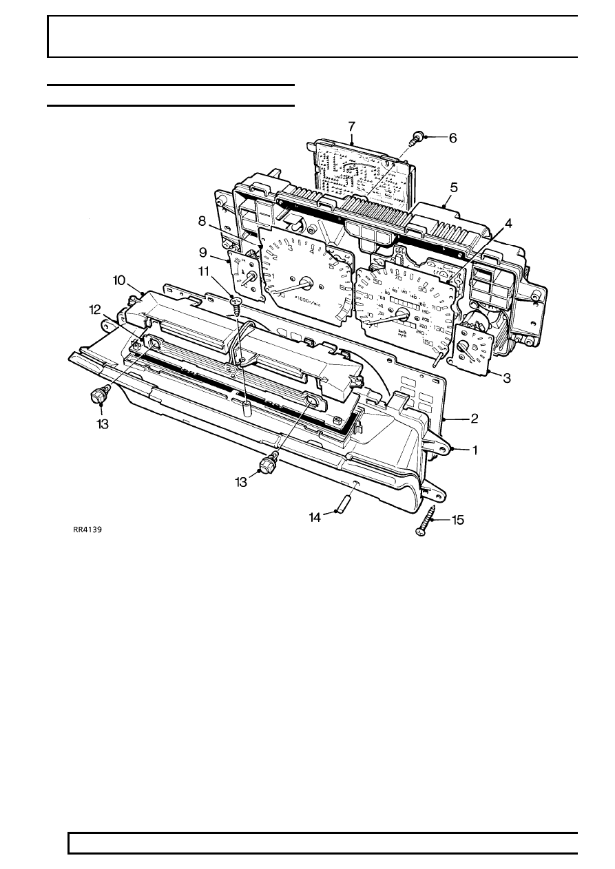
INSTRUMENT BINNACLE COMPONENTS

1. Instrument cowl
2. Face plate
3. Fuel gauge
4. Speedometer
5. Instrument binnacle
6. Screw - securing circuit board
7. Circuit board

8. Tachometer
9. Temperature gauge

10. Illumination board
11. Screw securing illumination board
12. Circuit board - instrument illumination
13. Instrument illumination bulb holder and bulb
14. Speedometer trip reset button sleeve
15. Screw - cowl and binnacle

ELECTRICAL

49

REPAIR

PRINTED CIRCUIT AND WARNING LIGHTS

1. Panel illumination bulbs
2. Transmission oil temperature warning lamp bulb
3. Hazard warning lamp bulb
4. Check engine warning lamp bulb
5. Handbrake/brake fluid warning lamp bulb
6. ABS warning lamp bulb
7. Headlamp main beam warning lamp bulb
8. Trailer direction warning lamp bulb

9. Direction indicator warning lamp bulb

10. Air suspension warning lamp bulb
11. Ignition/no charge warning lamp bulb
12. Seat belt warning lamp bulb
13. Not used
14. Traction control warning lamp bulb
15. Diesel heater plug warning lamp bulb (if fitted)
16. Main printed circuit

86

ELECTRICAL

50

REPAIR

INSTRUMENT COWL AND ILLUMINATION BOARD

Service repair no - 88.20.06 - Instrument cowl
Service repair no - 88.20.22 - Illumination board

Remove

1. Remove binnacle.

See Instrument Binnacle

Instrument cowl

2. Remove bulb holder from binnacle.
3. Release 4 clips securing top of cowl to binnacle.
4. Release 3 clips securing bottom of cowl to

binnacle, remove cowl.

Illumination board

5. Release bulb holder wires from clip.
6. Remove screw securing illumination board to

cowl, remove board.

Refit

Illumination board

7. Position illumination board to cowl, fit and tighten

screw.

8. Secure bulb holder wires in clip.

Instrument cowl

9. Ensure instrument face plate is correctly

positioned.

10. Position cowl to binnacle ensuring speedometer

trip passes through hole in cowl.

11. Secure cowl retaining clips.
12. Fit bulb holder in binnacle.
13. Fit binnacle.

See Instrument Binnacle

ELECTRICAL

51

REPAIR

SPEEDOMETER

Service repair no - 88.30.01

Remove

1. Remove instrument cowl.

See Instrument

Cowl and Illumination Board

2. Remove speedometer trip reset button sleeve.
3. Remove instrument face plate.
4. Remove 4 screws securing speedometer,

remove speedometer.

Refit

5. Reverse removal procedure.

TACHOMETER

Service repair no - 88.30.21

Remove

1. Remove circuit board.

See Circuit Board

2. Remove instrument cowl.

See Instrument

Cowl and Illumination Board

3. Remove speedometer trip reset button sleeve.
4. Remove instrument face plate.
5. Remove 3 screws securing tachometer to

binnacle, remove tachometer.

Refit

6. Reverse removal procedure.


Content   ..  188  189  190  191   ..