Range Rover Classic. Manual - part 188
86
ELECTRICAL
40
REPAIR
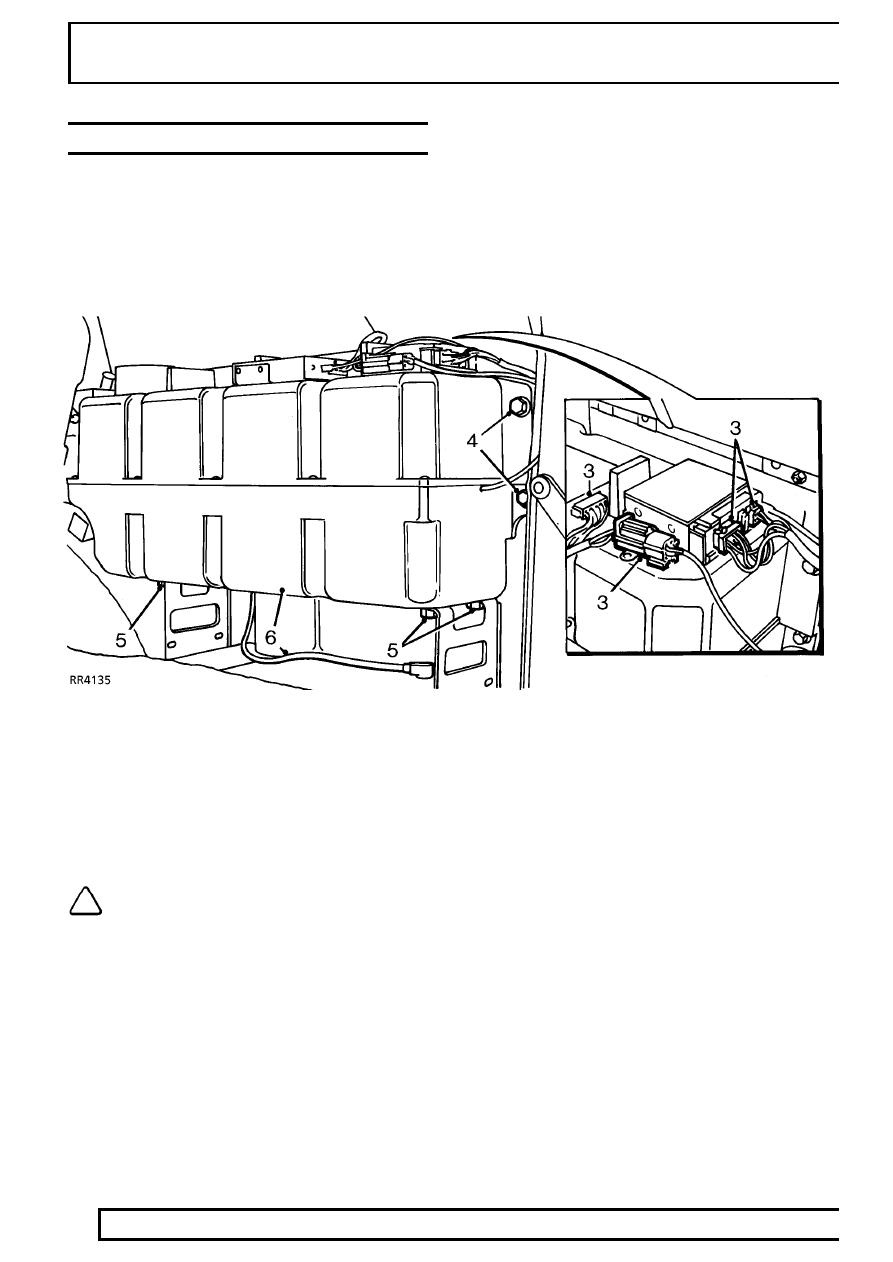
SUBWOOFER BOX
Service repair no - 86.50.51
Remove
1. Disconnect battery negative lead.
2. Remove rear parcel shelf RH support panel.
3. Disconnect multiplugs.
4. Remove 3 bolts securing side of subwoofer box
to body.
5. Remove 4 bolts securing bottom of subwoofer
box to body.
6. Withdraw subwoofer box, disconnect speaker
lead.
NOTE:
Do not carry out further
dismantling if component is removed for
access only.