Range Rover Classic. Manual - part 187


  Index      Land Rover     Range Rover Classic - service manual 1995 year


Search            


Content   ..  185  186  187  188   ..


Range Rover Classic. Manual - part 187


86

ELECTRICAL

36

REPAIR

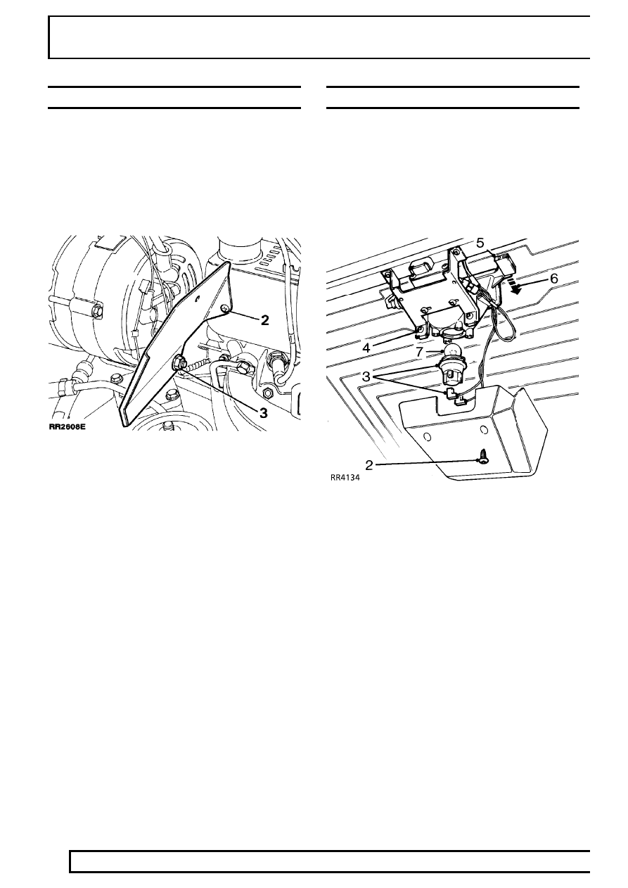
A.C. GENERATOR HEAT SHIELD

Remove

1. Disconnect battery negative lead.
2. Remove fixing screw.
3. Remove nut from A.C. generator rear mounting

bolt, remove heat shield.

Refit

4. Reverse removal procedure.

HIGH LEVEL STOP LAMP

Service repair no - 86.41.35

Includes bulb renewal
Service repair no - 86.41.34

Remove

1. Disconnect battery negative lead.

2. Remove two cover retaining screws. Remove

cover.

3. Disconnect electrical leads to bulb holder.

Remove bulbholder and bulb by twisting anti-
clockwise.

4. Remove two screws, mounting plate to stop

lamp.

5. Observe position of stop lamp on rear screen.

Carefully release tabs on stop lamp from rear
screen mountings.

6. Remove stop lamp.
7. Renew bulb if necessary.

Refit

8. Reverse removal procedure.

ELECTRICAL

37

REPAIR

ALARM HORN

Service repair no - 86.77.10

Remove

1. Remove decker panel.

See CHASSIS AND

BODY, Repair, Decker Panel

2. Disconnect two Lucar connectors.
3. Remove single nut securing horn.
4. Remove horn.

Refit

5. Reverse removal procedure.

GEAR SELECTOR-INTERLOCK

Interlock solenoid

Remove

1. Disconnect battery negative lead.
2. Remove gear selector head and illumination

panel.

See CHASSIS AND BODY, Repair,

Centre Console

3. Disconnect electrical multiplug.
4. Remove screws and lift gear selector

mechanism above housing.

5. Remove screws from microswitch support

bracket.

6. Remove screws and separate side cover from

housing.

7. Disconnect wiring solenoid to multiplug.
8. Remove circlip and retainer plate.
9. Remove clip and centre sleeve.

10. Refit clip into groove on spindle and lever

against it to remove solenoid from housing.

86

ELECTRICAL

38

REPAIR

Refit

11. Fit solenoid with wiring positioned into side cover

recess.

12. Fit sleeve and new clip.
13. Fit retaining plate and circlip.
14. Connect wiring to multiplug.
15. Apply sealant and fit side cover to housing. Use

Silcoset 152 sealant or equivalent.

16. Grease all moving parts of gear selector

mechanism. Use Rocol E1A or equivalent
grease.

17. Reverse instructions 1 to 5.

Interlock microswitch onto castellated plate.

Remove

1. Disconnect battery negative lead.
2. Remove gear selector head and illumination

panel.

See CHASSIS AND BODY, Repair,

Centre Console

3. Disconnect electrical multiplug.

4. Remove screws and lift gear selector

mechanism above housing.

5. Remove screws from microswitch support

bracket.

6. Remove screws and separate side cover from

housing.

7. Disconnect wiring microswitch to multiplug.

8. Remove 3 clips as shown.
9. Slide trunnion forward and remove gear selector

arm.

ELECTRICAL

39

REPAIR

10. Remove bolts securing coxcomb.
11. Remove microswitch retaining clip and

microswitch.

Refit

12. Reverse removal procedure. correctly

positioning microswitch.

13. Apply Loctite 242E to castellated plate bolts and

tighten to 9Nm .

14. Grease all moving parts of gear selector

mechanism. Use Rocol E1A or equivalent
grease.

15. Apply Silcoset 152 sealant or equivalent and fit

side cover to housing.

Interlock microswitch onto side cover

Remove

1. Disconnect battery negative lead.
2. Remove gear selector head and illumination

panel.

See Automatic Gear Selector-Panel

Bulb

3. Disconnect electrical multiplug.
4. Remove screws from microswitch support

bracket.

5. Disconnect wiring microswitch to multiplug.

Refit

6. Reverse removal procedure. Correctly

positioning microswitch.

7. Grease all moving parts of gear selector

mechanism. Use Rocol E1A or equivalent
grease.


Content   ..  185  186  187  188   ..