Range Rover Classic. Manual - part 191


  Index      Land Rover     Range Rover Classic - service manual 1995 year


Search            


Content   ..  189  190  191 


Range Rover Classic. Manual - part 191


86

ELECTRICAL

52

REPAIR

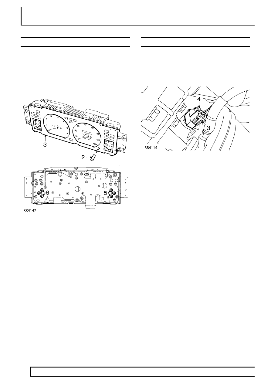
COOLANT TEMPERATURE AND FUEL GAUGES

Service repair no - 88.25.14 - Coolant temperature
gauge
Service repair no - 88.25.26 - Fuel gauge

Remove

1. Remove instrument cowl.

See Instrument

Cowl and Illumination Board

2. Remove speedometer trip reset button sleeve.
3. Remove instrument face plate.

Coolant temperature gauge

4. Remove circuit board.

See Circuit Board

5. Remove 3 screws securing coolant temperature

gauge to binnacle, remove gauge.

Fuel gauge

6. Remove 3 screws securing fuel gauge to

binnacle, remove gauge.

Refit

7. Reverse removal procedure.

SPEEDOMETER TRANSDUCER

Service repair no - 88.30.14

Remove

1. Position vehicle on ramp and chock wheels.
2. Raise ramp.

3. Disconnect multiplug from transducer.
4. Remove bolt securing transducer, remove

transducer.

Refit

5. Reverse removal procedure.

ELECTRICAL

53

REPAIR

ALARM ECU

Service repair no - 86.77.01

Remove

1. Remove lower dash panel,

See CHASSIS AND

BODY, Repair, lower dash panel

2. Remove multiplugs and aerial lead from ECU.

3. Remove relays and bases from bracket.
4. Remove ECU bracket fixings.
5. Remove ECU with bracket.

Refit

6. Reverse removal procedure. Aerial and

multiplugs must be fitted securely to ensure
alarm functions correctly.

ELECTRICAL

1

OVERHAUL

DISTRIBUTOR-LUCAS 35DLM8

Overhaul

DISTRIBUTOR CAP

Service repair no - 86.35.10

1. Unclip and remove cap
2. Fit a new cap if faulty.
3. Clean cap and HT brush with a lint free cloth.

ROTOR ARM

Service repair no - 86.35.16

1. Pull rotor arm from shaft.
2. Fit a new rotor arm if faulty.

INSULATION COVER (FLASH SHIELD)

Service repair no - 86.35.40

1. Remove cover secured by three screws.
2. Fit a new cover if faulty.

VACUUM UNIT

Service repair no - 86.35.21

1. Remove two screws from vacuum unit securing

bracket. Disengage vacuum unit connecting rod
from pick-up base plate connecting peg.
Withdraw vacuum unit from distributor body.

AMPLIFIER MODULE

Service repair no - 86.35.30

1. Remove two screws and withdraw module.
2. Remove gasket.
3. Remove two screws and cast heatsink.

WARNING: Amplifier module is a sealed
unit containing Beryllia. This substance is
extremely dangerous if handled. DO NOT

attempt to open or crush module.

PICK-UP AND BASE PLATE ASSEMBLY

Service repair no - 86.35.42

1. Use circlip pliers to remove circlip retaining

reluctor on rotor shaft.

2. Remove flat washer, and ’O’ ring recessed in top

of reluctor.

3. Gently withdraw reluctor from shaft, taking care

not to damage teeth.

NOTE: Coupling ring fitted beneath
reluctor.

4. Remove three support pillars and cable

grommet. Lift out pick-up and base plate
assembly.

NOTE: Do not disturb two barrel nuts
securing pick-up module, otherwise air
gap will need re-adjustment.

5. Fit a new pick-up and base plate assembly if

module is known to be faulty, otherwise check
pick-up winding resistance (2k-5k ohm).

Reassemble

6. This is mainly a reversal of dismantling

procedure, noting following points:

86

ELECTRICAL

2

OVERHAUL

LUBRICATION

Apply clean engine oil:

a.

A spot into rotor spindle before fitting rotor
arm.

Apply Omnilube 2 (or equivalent) grease.

b.

Auto advance mechanism.

c.

Pick-up plate centre bearing.

d.

Pre tilt spring and its rubbing area (pick-up
and base plate assembly).

e.

Vacuum unit connecting peg (pick-up and
base plate assembly).

f.

Connecting peg hole in vacuum unit
connecting rod.

Fitting pick-up and base plate assembly

1. Pick-up leads must be prevented from fouling

rotating reluctor. Both leads should be located in
plastic guide as illustrated. Check during
re-assembly.

Fitting reluctor

2. Slide reluctor as far as it will go on rotor shaft,

rotate reluctor until it engages with coupling ring
beneath pick-up base plate. Distributor shaft,
coupling ring and reluctor are ’keyed’ and rotate
together. Fit ’O’ ring, flat washer and retaining
circlip.

Pick-up air gap adjustment

1. Air gap between pick-up limb and reluctor teeth

must be set within specified limits, using a
non-ferrous feeler gauge.

2. If adjustment is necessary, slacken two barrel

nuts to set the air gap.

See ENGINE TUNING

DATA, Information, Engine - 3.9 V8i

NOTE: When original pick-up and base
plate assembly has been refitted, air gap
should be checked, and adjusted if

necessary.

When fitting a new assembly air gap will require
adjusting to within specified limits.

Amplifier module

1. Before fitting module, apply MS4 Silicone grease

or equivalent heat-conducting compound to
amplifier module backplate, seating face on
distributor body and both faces of heatsink
casting.


Content   ..  189  190  191