Range Rover Classic. Manual - part 48


  Index      Land Rover     Range Rover Classic - service manual 1995 year


Search            


Content   ..  46  47  48  49   ..


Range Rover Classic. Manual - part 48


19

FUEL SYSTEM

22

REPAIR

FUEL TANK

Service repair no - 19.55.01

WARNING: Ensure that fuel handling
precautions given in Section 01 -
introduction are strictly adhered to when

carrying out following instructions.

CAUTION: Before disconnecting any part
of fuel system, it is imperative that all dust,
dirt and debris is removed from around

components to prevent ingress of foreign matter
into fuel system.

Remove

1. Depressurise fuel system. Disconnect battery

negative lead.

2. Syphon fuel tank into a suitable container that

can be sealed afterwards.
ENSURE TANK IS DRAINED COMPLETELY.
(refer to Warning concerning fuel vapour and
spillage at start of procedure).

3. Remove carpet loadspace floor and tailgate.
4. Fold back sound insulation to reveal access

panel.

5. Remove access panel.
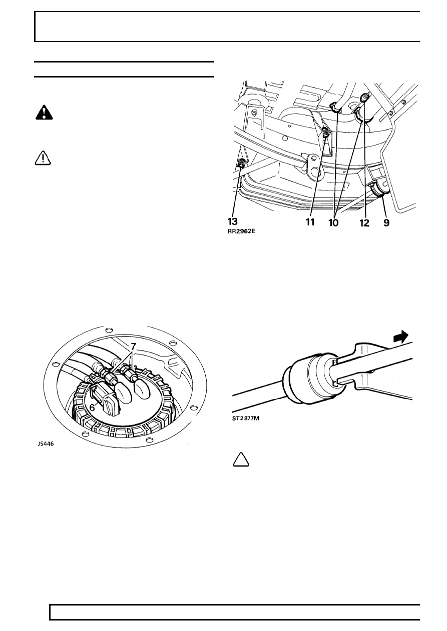
6. Disconnect electrical multi-plug.
7. Disconnect two fuel line unions from fuel pump.
8. Working underneath vehicle mark location of

anti-roll [sway] bar straps.

9. Remove rear anti-roll [sway] bar straps, and

allow bar to swing down clear of tank.

10. Remove tank filler and vent hoses at fuel tank.
11. Remove nut and bolt securing right hand side

fuel tank strap.

12. Disconnect evaporative control pipe at green

end of ’speedfit’ connector.

NOTE: To disconnect ’speedfit’ connector,
insert forked end of LRT-19-002 into slots
of connector see illustration. Press down

on collet and simultaneously pull pipe from
connector.

MFI

23

REPAIR

13. Remove back two bolts and nut plates securing

fuel tank cradle.

14. Remove front nuts, bolts and washers. Remove

fuel tank cradle.

15. With assistance, tilt right hand side of tank

upwards and manoeuvre tank through chassis to
remove.

Refit

16. Reverse removal procedure. Ensuring sealing

ring, fuel pipe and hose connections are secure.

17. Run engine, check all connections for fuel leaks.

FUEL FILLER FLAP RELEASE BUTTON

Service repair no - 19.55.23

On closing, filler flap will be locked automatically. Note
that release button will only work with ignition
switched to OFF or AUX.

Remove

1. Disconnect the battery negative lead.
2. Carefully pry release button from mirror switch

panel.

3. Remove release button from shroud and

disconnect tow wiring connectors. Ensure wires
protrude through panel for reassembly.

Refit

4. Reverse removal procedure.

19

FUEL SYSTEM

24

REPAIR

FUEL FILLER FLAP RELEASE ACTUATOR

Service repair no - 19.55.17

Remove

1. Release fuel filler flap. Disconnect the battery

negative lead.

2. Remove eight screws, with draw closure panel,

in right hand side of load space.

3. Release two screws and manoeuvre actuator

clear of its mounting.

4. Disconnect wiring plug.
5. Withdraw actuator.

Refit

6. Reverse removal procedure.

MFI

1

SPECIFICATIONS, TORQUE

TORQUE VALUES

NOTE: Torque wrenches should be regularly checked for accuracy to ensure that all fixings are
tightened to the correct torque.

Nm

Air-Bypass valve (stepper motor)

20

...............................................................

All flexible hose securing clamps

1,3

...............................................................

Fuel feed pipe - hose to fuel rail

22

.................................................................

Fuel filter

31

....................................................................................................

EVAPORATIVE LOSS CONTROL SYSTEM
All flexible hose securing clamps

1,7

...............................................................

METRIC

Nm

M5

6

......................................................................................................

M6

9

......................................................................................................

M8

25

.....................................................................................................

M10

45

...................................................................................................

M12

90

...................................................................................................

M14

105

..................................................................................................

M16

180

..................................................................................................

UNC / UNF

1/4

9

......................................................................................................

5/16

24

...................................................................................................

3/8

39

.....................................................................................................

7/16

78

...................................................................................................

1/2

90

.....................................................................................................

5/8

136

....................................................................................................

NOTE: Torque values above are for all screws and bolts used except for those specified.


Content   ..  46  47  48  49   ..