Range Rover Classic. Manual - part 46


  Index      Land Rover     Range Rover Classic - service manual 1995 year


Search            


Content   ..  44  45  46  47   ..


Range Rover Classic. Manual - part 46


19

FUEL SYSTEM

14

REPAIR

RAM HOUSING

Service repair no - 19.70.04

Remove

1. Disconnect battery negative lead.
2. Remove plenum chamber.

See Plenum

Chamber

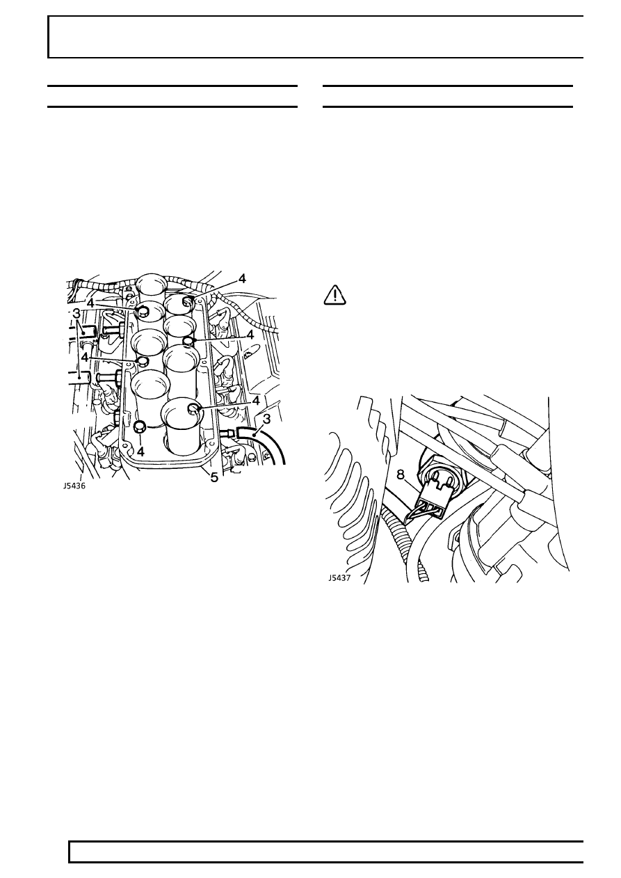
3. Release hoses from ram housing.
4. Remove six through bolts (with plain washers)

securing ram housing to intake manifold.

5. Remove ram housing from intake manifold.
6. Place a protective cover over inlet bores to

prevent ingress of dirt.

Refit

7. Clean all mating faces.
8. Apply ’Hylomar’ sealant to intake manifold face.
9. Fit ram housing. Tighten bolts, working from two

centre bolts, diagonally towards outer four bolts.

10. Tighten to

26 Nm.

INTAKE MANIFOLD

Service repair no - 30.15.08

Remove

1. Depressurise fuel system.

See Depressurising

Fuel System

2. Disconnect battery negative lead.
3. Drain cooling system.

See COOLING SYSTEM,

Repair, Radiator

4. Remove plenum chamber.

See Plenum

chamber

5. Remove ram housing.

See Ram Housing

CAUTION: Place a protective cover over
intake manifold openings to prevent the
ingress of dirt.

6. Disconnect the fuel temperature sensor and

injector multiplugs.

7. Remove fuel pressure regulator.

See Fuel

Pressure Regulator

8. Disconnect multiplug from coolant temperature

sensor.

9. Disconnect instrument pack temperature

thermistor.

10. Disconnect coolant sensor multiplug.

MFI

15

REPAIR

11. Loosen clip and disconnect top hose from

thermostat housing.

12. Disconnect multiplug from distributor amplifier

module.

13. Loosen clip and disconnect hose from heater

valve.

14. Remove injector harnesses from behind fuel rail

and lay to one side.

15. Loosen union and disconnect fuel return hose

from fuel rail.

NOTE: The intake manifold can be
removed from the cylinder block without
removing the fuel rail and injectors.

16. Using the sequence shown, remove 12 bolts

securing the intake manifold to cylinder block.

17. Remove the intake manifold.
18. Noting their fitted position, remove bolts and

clamps securing intake manifold gasket to
cylinder block.

19. Remove and discard gasket.
20. Remove and discard gasket seals.

Do not carry out further dismantling if component
is removed for access only.

21. Remove 5 nuts securing fuel rail support

brackets to intake manifold.

22. Remove fuel rail and injectors.
23. Remove 2 bolts securing thermostat housing to

intake manifold.

24. Remove thermostat housing.
25. Remove bolt securing coolant pipe to intake

manifold. Loosen union and remove coolant
pipe. Remove and discard ’O’ ring.

26. Fit new ’O’ ring to coolant pipe. Position coolant

pipe to intake manifold. Fit bolt securing coolant
pipe support bracket to intake manifold and
tighten pipe union.

27. Clean mating faces of thermostat housing and

intake manifold.

28. Fit thermostat housing to intake manifold using a

new gasket, fit and tighten bolts.

29. Position fuel rail to intake manifold, fit and

tighten retaining bolts.

19

FUEL SYSTEM

16

REPAIR

Refit

1. Clean mating faces of cylinder heads, cylinder

block and intake manifold.

2. Locate NEW seals in position with ends

engaged in notches formed between the cylinder
heads and block.

3. Apply RTV sealant between ends of seals,

cylinder head and block.

4. Fit intake manifold gasket with the word

’FRONT’ to the front and open bolts hole to the
front RH side.

5. Fit gasket clamps and tighten bolts finger tight.

6. Locate intake manifold onto cylinder heads,

clean threads of manifold securing bolts.

7. Allow 10 minutes for RTV sealant to cure.
8. Fit manifold bolts finger tight. Working in the

sequence shown tighten the bolts to

38 Nm.

9. Tighten the gasket clamp bolts to

18 Nm.

10. Reverse removal procedure.
11. Fill cooling system.

See COOLING SYSTEM,

Repair, Radiator

12. Start engine check for water and fuel leaks.

MFI

17

REPAIR

FUEL FILTER

Service repair no - 19.25.02

Remove

WARNING: Spilling of fuel is unavoidable
during this operation. Ensure all
necessary precautions are taken to

prevent fire and explosion.

WARNING: Ensure fuel handling
precautions given in Section 01 -
Introduction are strictly adhered to when

carrying out following instructions.

1. Depressurise fuel system.

See Depressurising

Fuel System

2. Access to filter is gained through right hand rear

wheel arch.

3. Clean area around hose connections to prevent

ingress of foreign matter into fuel system. Clamp
inlet and outlet hoses to prevent fuel spillage
when disconnecting hoses.

4. Loosen two fuel line unions and remove hoses.

Plug ends of hoses to prevent ingress of dirt.

5. Release securing bolt and bracket and remove

filter from chassis side member.

Refit

6. Fit a new filter observing direction of flow arrows

stamped on canister.

7. Tighten securing nut and bolt.
8. Fit inlet and outlet hoses. Tighten to

30Nm.

9. Refit fuel pump relay module, reconnect battery.

10. Start engine and inspect for fuel leaks around

hose connections.


Content   ..  44  45  46  47   ..