Range Rover Classic. Manual - part 45
19
FUEL SYSTEM
10
REPAIR
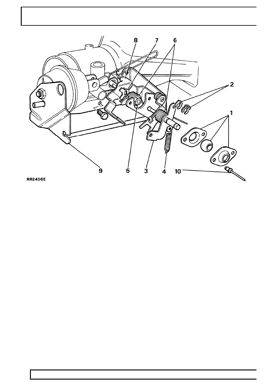
KEY
1. Spherical bush/housing
2. Retaining clips (2)
3. Countershaft assembly
4. Overtravel spring
5. Throttle shaft nut
6. Throttle return spring (2)
7. Tab washer
8. Throttle stop lever
9. Throttle bracket assembly
10. Pop rivets (2)