Range Rover. Manual - part 239
CHASSIS AND BODY
51
REPAIR
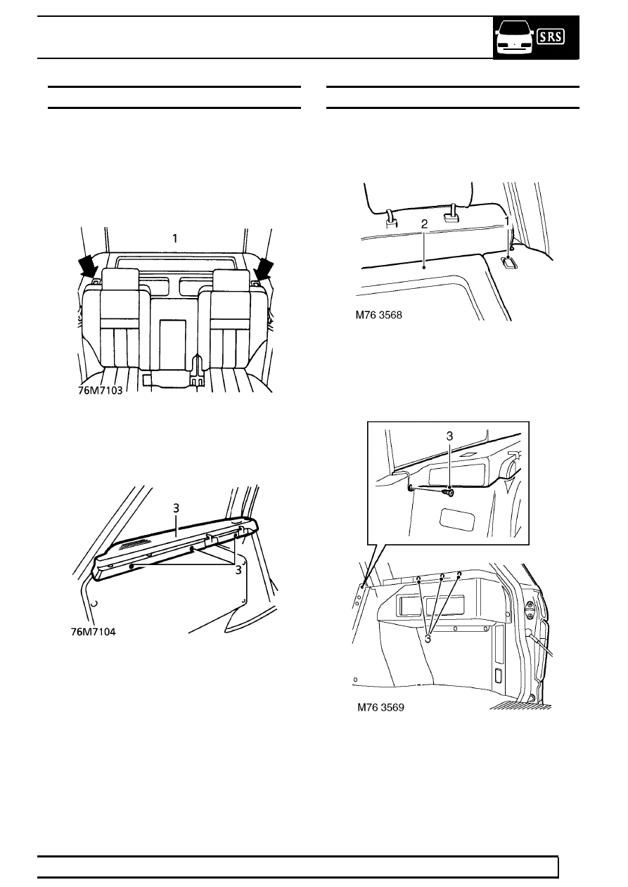
PARCEL TRAY SUPPORT
Service repair no - 76.67.11
Remove
1. Release 2 squab catches and fold rear seats
forward.
2. Remove parcel tray.
3. Remove 3 studs securing parcel tray support.
Remove support.
Refit
4. Reverse removal procedure.
PARCEL TRAY SUPPORT - FROM 2000MY
Service repair no - 76.67.11
Remove
1. Release 2 squab catches and fold rear seats
forward.
2. Remove parcel tray.
3. Remove 3 studs and 1 screw securing parcel
tray support.