Range Rover. Manual - part 59


  Index      Land Rover     Range Rover P38 - service manual 1995 year


Search            


Content   ..  57  58  59  60   ..


Range Rover. Manual - part 59


LAND ROVER V8

55

REPAIR

Refit

14. Use a suitable gasket removal spray and plastic

scraper to clean cylinder head and cylinder block
mating faces. Ensure bolt holes are left clean
and dry.

CAUTION: Do not use metal scraper or
machined surfaces may be damaged.

15. Check head and block faces for warping and

pitting.

16. Fit cylinder head gasket with the word TOP

uppermost.

NOTE: Gasket must be fitted dry.

17. Carefully fit cylinder head and locate on dowels.
18. Lightly lubricate new cylinder head bolt threads

with clean engine oil.

NOTE: Long bolts: 1, 3, 5. short bolts: 2, 4,
6, 7, 8, 9, 10.

19. Fit bolts and tighten in the sequence shown to

20 Nm (15 lbf.ft) then 90

°

, then a further 90

°

.

20. Clean push rods.
21. Lubricate ends of push rods with clean engine

oil.

22. Fit push rods in their removed order.
23. Clean base of rocker pillars and mating face on

cylinder head.

24. Clean contact surface on rockers, valves and

push rods.

25. Lubricate contact surface and rocker shaft with

clean engine oil.

26. Fit rocker shaft assembly and engage push rods.

Tighten bolts progressively to

38 Nm (28 lbf.ft).

27. Fit rocker cover.
28. Position alternator mounting bracket, fit and

tighten bolts to

40 Nm (30 lbf.ft).

29. Position engine harness, align oil cooler pipe

and secure with bolt.

30. Position auxiliary drive belt tensioner, fit bolt and

tighten to

45 Nm (33 lbf.ft).

31. Position engine earth lead, fit bolt and tighten to

22 Nm (16 lbf.ft).

32. Connect HT leads to spark plugs.
33. Fit exhaust manifold gasket.

See MANIFOLD

AND EXHAUST SYSTEM, Repair.

34. Fit inlet manifold gasket.

See MANIFOLD AND

EXHAUST SYSTEM, Repair.

35. Remove stand(s) and lower vehicle.

TIMING CHAIN AND GEARS - from 99MY

Service repair no - 12.65.12

Remove

1. Remove front cover gasket.

See this section.

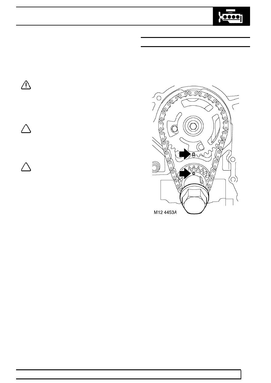
2. Fit crankshaft pulley bolt and rotate engine to

align timing marks. Remove crankshaft pulley
bolt.

12

ENGINE

NEW RANGE ROVER

56

REPAIR

3. Restrain camshaft gear and remove gear

retaining bolt.

4. Remove camshaft drive chain and gears as an

assembly.

5. Remove gears from chain.
6. If necessary remove key from crankshaft.

Refit

7. Clean timing chain, gears and gear locations.
8. Fit key to crankshaft.
9. Temporarily fit gears to camshaft and crankshaft.

If necessary, rotate shafts to align timing marks.

NOTE: When aligned correctly, the timing
marks will face each other: the crankshaft
gear with its timing mark at twelve 0’clock

position and the camshaft with its timing mark at
six 0’clock position.

10. Remove gears from shafts and fit to timing

chain.

11. With timing marks aligned, fit timing chain and

gears as an assembly.

12. Restrain the camshaft gear and tighten retaining

bolt to

50 Nm (37 lbf.ft).

13. Fit front cover gasket

See this section.

14. Reconnect battery negative lead.

17 - EMISSION CONTROL

CONTENTS

Page

DESCRIPTION AND OPERATION

EMISSION CONTROL - BMW DIESEL

1

................................................................

EMISSION CONTROL - LAND ROVER V8

5

.........................................................

SECONDARY AIR INJECTION SYSTEM

12

..........................................................

EVAPORATIVE CONTROL SYSTEM - PRE ADVANCED EVAPS

16

...................

EVAPORATIVE EMISSION CONTROL SYSTEM - ADVANCED EVAPS

(up to 99MY)

18

.......................................................................................................

EVAPORATIVE EMISSION CONTROL SYSTEM - ADVANCED EVAPS

(from 99MY)

19

.......................................................................................................

EXHAUST EMISSION CONTROL COMPONENTS - (from 99MY)

23

...................

SECONDARY AIR INJECTION SYSTEM COMPONENTS

26

...............................

EVAPORATIVE EMISSION SYSTEM CONTROL COMPONENTS - (from

99MY)

31

.................................................................................................................

FAULT DIAGNOSIS

TESTING EVAPORATIVE EMISSION CONTROL - PRE ADVANCED

EVAPS

1

.................................................................................................................

LEAK DETECTION PROCEDURE - ADVANCED EVAPS

1

..................................

DRIVE CYCLES - up to 99MY

2

.............................................................................

DRIVE CYCLES - from 99MY

2

..............................................................................

REPAIR

CATALYST HEAT SHIELDS

1

................................................................................

EVAP CANISTER - PRE-ADVANCED EVAPS

1

....................................................

EVAP CANISTER - ADVANCED EVAPS (up to 99MY)

2

.......................................

EVAP CANISTER - from 99MY

3

............................................................................

EVAP CANISTER - LEVS

4

....................................................................................

PURGE VALVE - up to 97MY

5

..............................................................................

PURGE VALVE - 97MY to 99MY

5

.........................................................................

PURGE VALVE - from 99MY

6

...............................................................................

EVAP CANISTER VENT SOLENOID - up to 99MY

6

.............................................

EVAP CANISTER VENT SOLENOID - from 99MY

7

..............................................

EXHAUST GAS RECIRCULATION (EGR) VALVE - DIESEL

8

..............................

MODULATOR VALVE - EGR

8

...............................................................................

VACUUM PUMP - EGR SYSTEM

9

........................................................................

SOLENOID - EVAP CANISTER VENT VALVE

10

..................................................

CONTROL VALVE - SECONDARY AIR INJECTION (SAI)

10

...............................

RESERVOIR - VACUUM - SECONDARY AIR INJECTION (SAI)

11

......................

PUMP - SECONDARY AIR INJECTION (SAI)

11

...................................................

AIR MANIFOLD - LH - SECONDARY AIR INJECTION (SAI)

12

............................

17 - EMISSION CONTROL

CONTENTS

Page

AIR MANIFOLD - RH - SECONDARY AIR INJECTION (SAI)

12

...........................

SOLENOID - VACUUM - SECONDARY AIR INJECTION (SAI)

13

........................

PIPE - SECONDARY AIR INJECTION (SAI)

13

.....................................................


Content   ..  57  58  59  60   ..