Frelander 2. Manual - part 577


  Index      Land Rover     Land Rover Frelander 2 - service repair manual 2006-2010 year


Search            


Content   ..  575  576  577  578   ..


Frelander 2. Manual - part 577


Handles, Locks, Latches and Entry Systems - Handles, Locks, Latches and
Entry Systems

Description and Operation

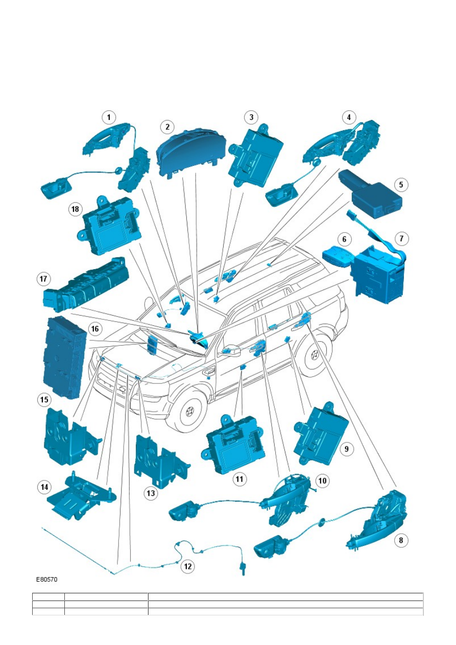
COMPONENT LOCATION (SHEET 1 OF 2)

• NOTE: Left-Hand Drive (LHD) shown; Right-Hand Drive (RHD) similar.

Item

Part Number

Description

1

-

Right-Hand (RH) front door handle and latch

2

-

Instrument cluster

3

-

RH rear door control module

4

-

RH rear door handle and latch

5

-

Radio Frequency (RF) receiver

6

-

Remote handset

7

-

Start control module

8

-

Left-Hand (LH) rear door handle and latch

9

-

LH rear door control module

10

-

LH front door handle and latch

11

-

LH front door control module

12

-

Hood release cable

13

-

LH hood latch

14

-

Hood safety hook

15

-

RH hood latch and ajar switch

16

-

Central Junction Box (CJB)

17

-

Instrument panel central locking switches

18

-

RH front door control module

COMPONENT LOCATION (SHEET 2 OF 2)

• NOTE: LHD shown; RHD similar.

Item

Part Number

Description

1

-

Liftgate release switch

2

-

Auxiliary Junction Box (AJB)

3

-

Fuel filler door actuator

4

-

Liftgate latch and ajar switch

OVERVIEW

All the vehicle hinged panels are secured by latches with mating strikers. The latches incorporate panel ajar switches that
will inform the driver of an open access point.

The central locking system is operated by either the remote handset, front door central locking buttons or the instrument
panel central locking switches. The central locking system controls the automatic locking and unlocking of the vehicle entry
points. The software used to control the central locking system is incorporated within the CJB.

The central locking system is also integrated with the interior lighting function. The interior lights and exterior mirror lamps
are illuminated via the RF receiver and CJB following a valid unlock request from the remote handset.
For additional information, refer to: 

Interior Lighting

 (417-02 Interior Lighting, Description and Operation).

If configured by the dealer, the exterior door mirror power fold function is also operated by the central locking system.

A concealed mechanical door lock is provided in the front LH door exterior handle, and is used to gain access to the vehicle if
the battery is discharged or the central locking system fails.

DOOR LATCHES

Item

Part Number

Description

1

-

Door interior lock/unlock button

2

-

Door interior release handle

3

-

Mechanical door lock release cable (front LH door only)

4

-

Door lock exterior release cable

5

-

Door striker

6

-

Emergency mechanical door lock (front LH door only)

7

-

Exterior door handle lock cover

8

-

Exterior door handle

9

-

Door latch

10

-

Electrical connection to door control module

11

-

Door lock interior release cable

The door latches are installed at the rear edge of each door and engage with corresponding strikers mounted to the 'B' and
'C' pillars. Each interior and exterior door handle is connected with a release cable to the corresponding door latch. In the
front LH door a third release cable is connected between the door latch and the concealed emergency mechanical door lock.

Each door latch is a sealed unit that comprises the following:

Lock motor
Double lock motor (all except North American Specification (NAS), Japan and Gulf vehicles)
Door ajar switch.

An electrical connector is incorporated in each door latch and provides the interface with the door control module, CJB, and
AJB. The front door control modules are connected to the CJB on the medium speed Controller Area Network (CAN) bus; the
rear door control modules are connected via the Local Interconnect Network (LIN) bus to the front door control modules.
Power supply for the door latch lock and double lock motors is provided from the AJB.

The lock and double lock motors control the engagement of the door latches with the release cables to lock and unlock the
vehicle. When the vehicle is locked, the lock motors disengage the door latches from the exterior release cables. When the
vehicle is double locked, the double lock motors also disengage the door latches from the interior release cables. When the
vehicle is subsequently unlocked, the interior and exterior release cables are re-engaged with the door latches.

All the door interior release handles incorporate a locking button. When a front door central locking button is pressed/pulled,
all the vehicle doors will centrally lock/unlock. When a rear door locking button is pressed/pulled, the locking button will only
lock/unlock the activated rear door.

When the door locking button is pressed, the interior release cable is pushed and causes the exterior release cable to be
disengaged from the door latch. On the rear doors, pressing the locking button will also disengage the interior handle from
the interior release cable.

When the door locking button is pulled away from the door, the door interior release handle is re-engaged with the interior
release cable. As the interior release cable is re-engaged it is pulled, causing the door latch to re-engage with the exterior
release cable.

Rear Door Child Locks

The rear door latches incorporate child locks that provide additional rear occupancy safety. The child locks are manually
operated using the emergency key blade within the remote handset. Setting the child lock to the locked position will
disengage the door latch interior release cable from the door latch, and prevent opening of the rear door using the interior
release handle.

For further information on child locks, refer to the Owners Handbook.

Door Ajar Switch

An ajar switch is installed in each door latch and is hardwired to the CJB. If the ignition is in power modes 4 (Accessory) or 6
(Ignition) and a door is opened or is not fully closed, the corresponding door ajar switch is opened to disconnect the ground
from the CJB. A message is transmitted by the CJB via the medium speed CAN bus to the instrument cluster, to inform the
driver that a door is ajar.

On vehicles with a low-line instrument cluster the door ajar symbol is illuminated.
For additional information, refer to: 

Instrument Cluster

 (413-01 Instrument Cluster, Description and Operation).

On vehicles with a high-line instrument cluster, the door ajar symbol is illuminated and a message is also displayed in the
message center.
For additional information, refer to: 

Information and Message Center

 (413-08 Information and Message Center, Description

and Operation).

The door ajar switch is also integrated with the vehicle security system and is used as the detection device for unauthorized
vehicle entry.
For additional information, refer to: 

Anti-Theft - Active

 (419-01A Anti-Theft - Active, Description and Operation).

Emergency Mechanical Door Lock

Item

Part Number

Description

1

-

Concealed mechanical lock


Content   ..  575  576  577  578   ..