Frelander 2. Manual - part 578


  Index      Land Rover     Land Rover Frelander 2 - service repair manual 2006-2010 year


Search            


Content   ..  576  577  578  579   ..


Frelander 2. Manual - part 578


2

-

Emergency key blade

3

-

LH front door handle

The remote handset contains an emergency key blade, concealed in the key fob. The front LH exterior door handle
incorporates a mechanical operated door lock that is concealed behind a removable plastic cover. The door lock allows the
front LH door to be mechanically unlocked and locked using the emergency key blade in the event that the remote central
locking operation fails, or a vehicle power failure occurs.

When the mechanical door lock is used the central locking system will not operate, and if already armed the vehicle alarm
will sound when the door is opened. The vehicle is not able to be double locked, or the alarm system armed using the
emergency key blade.
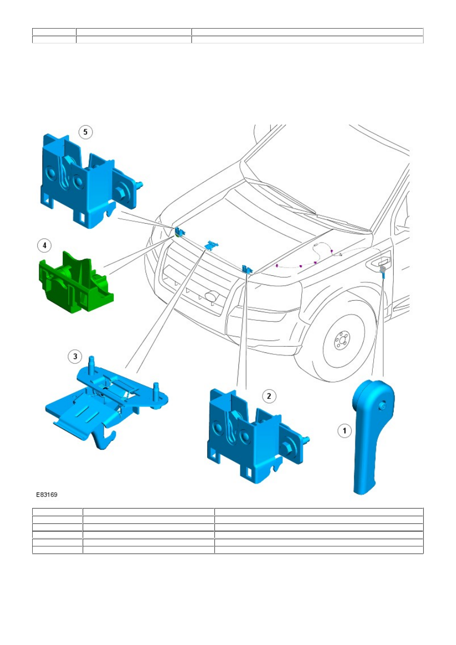
HOOD LATCHES

Item

Part Number

Description

1

-

Hood release handle

2

-

LH hood latch

3

-

Hood safety hook

4

-

Hood ajar switch

5

-

RH hood latch

The hood is secured in the closed position by 2 latches located on each side of the hood latch panel. The hood release lever
is located below the instrument panel on the LH 'A' pillar and is connected with a cable to the hood latches. Operation of the
hood release lever will open the 2 hood latches and release the hood.

A mechanically operated safety hook is installed at the front center of the hood. The safety hook prevents the hood from
fully opening in the event that the hood latches are open, and the vehicle is in motion. The safety hook is spring operated
to bias the hook to the latched position, and is formed with a lever plate. The lever must be pressed to release the safety
hook from the mating latch plate when the hood is to be fully opened.

Hood Ajar Switch

The RH hood latch incorporates the hood ajar switch that is hardwired to the CJB. If the ignition is in power modes 4
(Accessory) or 6 (Ignition) and the hood is opened or is not fully closed, the hood ajar switch is opened to disconnect the
ground from the CJB. A message is transmitted by the CJB via the medium speed CAN bus to the instrument cluster, to
inform the driver that the hood is ajar.

On vehicles with a low-line instrument cluster the hood ajar symbol is illuminated.
For additional information, refer to: 

Instrument Cluster

 (413-01 Instrument Cluster, Description and Operation).

On vehicles with a high-line instrument cluster, the hood ajar symbol is illuminated and a message is also displayed in the
message center.
For additional information, refer to: 

Information and Message Center

 (413-08 Information and Message Center, Description

and Operation).

The hood ajar switch is also integrated with the vehicle security system and is used as the detection device for unauthorized
vehicle entry.
For additional information, refer to: 

Anti-Theft - Active

 (419-01A Anti-Theft - Active, Description and Operation).

LIFTGATE LATCH

Item

Part Number

Description

1

-

Liftgate latch

2

-

Liftgate striker

The liftgate latch is mounted at the bottom center of the liftgate interior body panel and is a fully electrically operated unit.
The liftgate latch incorporates the liftgate lock motor, and receives a power supply via a hardwired connection from the CJB.
A release microswitch is housed within a touch-pad that is located on the underside of the liftgate exterior handle.

The liftgate latch is released by the CJB when the vehicle is stationary and either the remote handset button is pressed, or
the exterior handle touch-pad is applied. The liftgate latch is also released when the instrument panel central locking
switches are simultaneously pressed for 3 seconds, and the vehicle speed is less than 8 km/h (5 mph).

Liftgate Ajar Switch

The liftgate latch also incorporates the liftgate ajar switch that is hardwired to the CJB. If the ignition is in power modes 4
(Accessory) or 6 (Ignition) and the liftgate is opened or is not fully closed, the liftgate ajar switch is opened to disconnect
the ground from the CJB. A message is transmitted by the CJB via the medium speed CAN bus to the instrument cluster, to
inform the driver that the liftgate is ajar.

On vehicles with a low-line instrument cluster the liftgate ajar symbol is illuminated.
For additional information, refer to: 

Instrument Cluster

 (413-01 Instrument Cluster, Description and Operation).

On vehicles with a high-line instrument cluster, the liftgate ajar symbol is illuminated and a message is also displayed in
the message center.
For additional information, refer to: 

Information and Message Center

 (413-08 Information and Message Center, Description

and Operation).

The liftgate ajar switch is also integrated with the vehicle security system and is used as the detection device for
unauthorized vehicle entry.
For additional information, refer to: 

Anti-Theft - Active

 (419-01A Anti-Theft - Active, Description and Operation).

FUEL FILLER DOOR ACTUATOR

The fuel filler door is electrically locked and unlocked with an actuator and plastic pin. The actuator is located behind the
fuel filler door housing, and operates the pin to engage or release a spigot on the door mounting hinge arm.

The fuel filler door actuator is hardwired to the CJB and is operated by the vehicle central locking system. The CJB reverses
the polarity of the actuator power and ground connections, allowing the pin to move in both directions for locking and
unlocking. When unlocked, the fuel filler door is manually opened to gain access to the fuel tank filler cap.

CENTRAL LOCKING SYSTEM CONTROLS

The central locking system provides the driver with control over the locking and unlocking of the vehicle entry points, from
inside or outside the vehicle. Manual operation of the central locking system is achieved using the following:

Remote handset and RF receiver
Front door central locking button
Instrument panel central locking switches.

Remote Handset

Item

Part Number

Description

1

-

Emergency key blade

2

-

Headlamp delay function button

3

-

Vehicle lock button

4

-

Vehicle unlock button

5

-

Liftgate unlock button

6

-

Panic alarm button

The remote handset is a sealed waterproof unit that contains a Printed Circuit Board (PCB), transponder and a rechargeable
battery. The remote handset battery is charged whenever the remote handset is located in the start control unit, and the
engine is running.

The remote handset contains an emergency key blade, concealed in the key fob. The emergency key blade is used to access
the vehicle through the LH front door if the central locking system fails. The emergency key blade is also used to enable or
disable the rear door child locks, and to disable the passenger airbag.
For additional information, refer to: 

Air Bag and Safety Belt Pretensioner Supplemental Restraint System (SRS)

 (501-20B

Supplemental Restraint System, Description and Operation).

The remote handset is identical for all vehicle specifications, but differs in the preset frequency and power that the remote
handset operates. The remote handset for each vehicle specification is identified by a suffix change to the base part number
as follows:

Part No. Suffix

Operating Frequency

Vehicle Specification

A#

433 MHz

Europe and ROW (Rest Of World)

B#

315 MHz

NAS

C#

315 MHz low power

Japan and Korea

Each remote handset features a unique identification code that is programmed within the integral transponder. The RF signal
produced by the remote handset contains the unique identification code and also a rolling code. During vehicle production,
the unique identification codes of the valid remote handsets are programmed into the CJB, and the rolling codes are also
synchronized with the CJB.

When the remote handset is operated, the CJB checks the unique identification and rolling code. The CJB will only respond if
the RF signal produced is from a valid remote handset for the vehicle.
For additional information, refer to: Anti-Theft - Passive (419-01 Anti-Theft - Passive, Description and Operation).

A total of 30 'slots' are available in the CJB software to allow for replacement, and the addition of remote handsets. In
service, the Land Rover approved diagnostic system may be used to communicate with the CJB for the following:

Identification of remote handset allocation within the CJB.
Enabling of new remote handsets.
Disabling of existing remote handsets.
Re-enabling a previously disabled remote handset.

If the remote handset rolling code loses synchronization with the CJB, the remote handset functions will not operate.
Synchronization between the remote handset and CJB is restored by starting the engine with the affected remote handset,
and allowing the engine to run for a minimum of 6 minutes.

Additional buttons are located on the remote handset to provide convenience operation of the liftgate release, headlamp
delay and panic alarm functions.


Content   ..  576  577  578  579   ..