Frelander 2. Manual - part 489
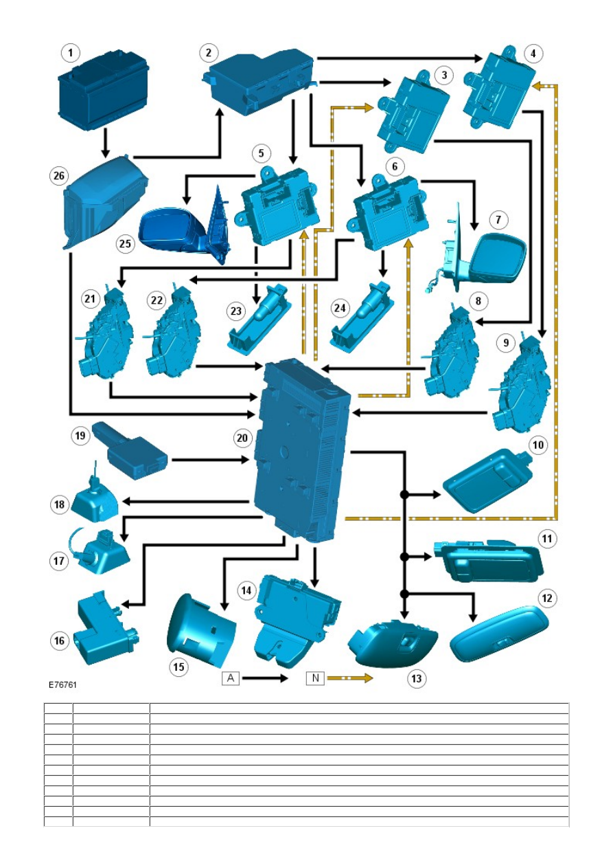
Item
Part Number
Description
1
-
Battery
2
-
Auxiliary Junction Box (AJB)
3
-
Rear door module
4
-
Rear door module
5
-
Driver door module
6
-
Passenger door module
7
-
Exterior mirror lamp
8
-
Rear door latch switch
9
-
Rear door latch switch
10
-
Vanity mirror lamp
11
-
Vanity mirror lamp