Frelander 2. Manual - part 455


  Index      Land Rover     Land Rover Frelander 2 - service repair manual 2006-2010 year


Search            


Content   ..  453  454  455  456   ..


Frelander 2. Manual - part 455


6. BATTERY CHARGING AND MAINTENANCE
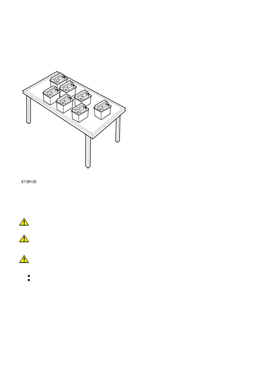
BATTERY CHARGING

It is essential that a suitably ventilated defined area exists in each dealership / retailer for battery charging. Likewise, an
area should be allotted for scrap batteries, and clearly indicated as such. It is recommended that dealers / retailers always
have fully charged batteries ready for use. However the battery MUST BE tested and charged if necessary every month, and
charged after three months irrespective of any test.

• CAUTIONS:

 Batteries must be re-charged after a maximum of 3 months storage (see Storage History sheet in the New Vehicle

Storage Manual).

 It is very important that when charging batteries using the traction charger or other stand-alone chargers that the

charger is set for the correct type of battery before charging commences. If the wrong switch is selected the result would
be a battery that is not charged fully and / or overheating can occur. Follow the manufacturers operating instructions.

 Do not charge AGM batteries with voltages over 14.8 volts as this will damage the battery.

To bring a serviceable but discharged battery back to a fully charged condition proceed as follows:

Check and if necessary top-up the battery electrolyte level.
Charge the battery using the Midtronics Diagnostic Charger (USA) or Traction Charger (all other markets) following
the manufacturers operating instructions.

• NOTE: When using the Midtronics Diagnostic Charger, automatic mode must always be used. After charging and analysis,
the charger may display ‘Top-Off Charging’, press STOP to end. Do not stop charging until the current falls to 5A or less,
otherwise the battery will not be fully charged.

POST-CHARGE TEST METHODS

New Batteries, Batteries in Storage and In-Service Batteries

The purpose of this test is to ensure that the charging process has fully charged the battery.

• NOTE: IT IS RECOMMENDED THAT THIS TEST IS CONDUCTED AT LEAST 24 HOURS AFTER THE CHARGE CYCLE IS
COMPLETED.

CAUTION: DO NOT connect the tester to any other circuit or chassis point.

1. Attach the Midtronics Tester to the battery.

2. Follow the instructions on the tester to test the battery. Ensure the correct battery type and size is selected.

3. Perform the action based on the tester results (see the tester results chart in the Vehicles in Service sub -section of
Determining Battery Condition Section).

4. Enter the readings and test code obtained on the In Service Battery Report Form.

• NOTE: Midtronics 393, 394. 493 and 494 testers must not be used to test AGM batteries as these testers are not capable
of correctly testing AGM batteries and can give an incorrect result. For AGM battery testing use the EXP1080 tester or the
GR1 Diagnostics charger.

BATTERY REPLACEMENT

If it is determined that a battery requires replacement, always refer to the appropriate section of the workshop manual for
instructions on removing and installing the battery from the vehicle.

On in service vehicles fitted with a Battery Monitoring System (BMS), the BMS module must be reset following the
installation of a new battery. The BMS module reset procedure must be performed using an approved diagnostic system.

CHECK/TOP-UP BATTERY ELECTROLYTE – Only Applicable to certain Flooded Types of Battery.

• W ARNINGS:

 AGM TECHNOLOGY BATTERIES ARE FULLY SEALED FOR LIFE AND NO ATTEMPT SHOULD BE MADE TO CHECK OR TOP

UP THE ELECTROLYTE LEVEL.

 BEFORE CHECKING AND TOPPING-UP THE BATTERY ELECTROLYTE, REFER TO THE HEALTH AND SAFETY

PRECAUTIONS SECTION.

Check to ensure the battery is of a type suitable for topping up. These types of batteries will have cell plugs visible on the
top face of the battery or a removable access panel to allow access to the cells.

On batteries with a clear or opaque case and level marks, check the electrolyte level by visual inspection of the maximum
level indicator mark on the battery casing indicating adequate level above the battery separators.

On batteries with black cases, remove the cell plugs or access panel and ensure the electrolyte level is level with the
indicator in the cell hole. A flashlight may be required to see the electrolyte level on this type of battery.

CAUTION: DO NOT overfill.

If the electrolyte level is low, top-up using distilled water.

Maintenance free and Valve Regulated (AGM) batteries are sealed and therefore cannot be topped up.

CHARGING SYSTEM TEST AND DIAGNOSIS

For all vehicles, refer to the Charging System - Diagnosis and Testing in section 414-00 of the W orkshop Manual.

VEHICLE QUIESCENT CURRENT TESTING

• NOTE: On vehicles fitted with a Battery Monitoring System (BMS), the diagnostic routine for quiescent drain testing in
the approved diagnostic system should be utilized.

• NOTE: If a customer complains of a vehicle battery that discharges continuously or when left for a prolonged period of
time, it is recommended that a quiescent drain test is performed as described below.

• NOTE: The battery drain should be measured using an approved diagnostic system or a Digital Multi-Meter (DVOM).

The vehicle should be in the locked/armed state (for example vehicle alarm fully armed), all doors, engine and luggage
compartment lids are open and latched (so as to appear closed from an electrical point of view). The test should take
place after the vehicle has entered shutdown mode. The time taken for this to occur after the ignition is switched off
varies according to model - Refer to Quiescent Drain in section 414-00 of the Workshop Manual.

• NOTE: When the vehicle is armed, the effect of the security system Light Emitting Diode (LED) flashing is to cause a
pulsation in the measured current drain. In this case, either the average current should be taken (using a Digital Multi-
Meter (DVOM) with an averaging system) or the current reading taken, ignoring the brief high current peaks.

EQUIPMENT

Approved diagnostic system with current probe or Digital Multi-Meter (DVOM) with current probe.

METHOD OF MEASUREMENT

Using an Approved Diagnostic System

1. Switch off all electrical loads and ensure that the ignition is off.

2. Connect the current probe to the approved diagnostic system.

3. Calibrate the probe.

4. Install a clamp around the battery lead/junction box lead.

5. Go to the Quiescent Current Testing section.

Using a Digital Multi-Meter (DVOM)

• NOTE: Do not use an in-line DVOM to measure the quiescent drain on vehicles fitted with an electronic throttle. The
current exceeds the maximum amount the fuse in the DVOM is capable of handling.

1. Switch off all electrical loads and ensure that the ignition is off.

2. Connect the current probe to the DVOM.

3. Calibrate the probe.

4. Install a clamp around the battery lead/junction box lead.

5. Go to the following Quiescent Current Testing section.

QUIESCENT CURRENT TESTING

1. Switch ignition to ‘on’ or select ignition mode in keyless vehicles and switch to ‘off’ (do not crank).

2. Remove key from ignition switch (where applicable).

3. Open and latch all doors, hood and luggage compartment lid.

4. Lock the vehicle using the remote function on the remote handset. (Single lock only to avoid volumetric alarm arming).

5. Remove any other potential electrical drains such as accessories plugged into accessory sockets.

6. Record the amperage readings after the shutdown period. The model specific Amperage readings for quiescent drain are
referenced in Quiescent Drain in section 414-00 of the Workshop Manual

7. Record the final reading on the battery report form Appendix B.

• NOTE: The preferred method of testing following an excessive current consumption figure is to use a current probe
around individual junction box leads to the various suspected circuits to identify a potential cause. This is in preference to
the old method of removing fuses for the following reasons:

Many modules take a considerable time to power down. Each time a fuse is removed and re-fitted, the quiescent
drain current may take an extended period of time to return to normal (typically up to 45 minutes).
The drain may be caused by a module remaining active and preventing the quiescent drain from reducing to normal
levels.
The drain may be caused by a relay winding that is activated. Pulling the fuse can allow this to ‘reset’ and the drain
will be lost and go un-diagnosed.

APPENDIX A BATTERY TEST PROCESS

It is recommended that this test is conducted at least 24 hours after the vehicle engine has been run or the battery
charged to avoid the need of surface charge removal or if this time constraint is unacceptable due to circumstances, then
conduct the charge strip removal process.

Part 1 - Surface Charge Removal

• NOTE: Before carrying out a battery test you must ensure that there is no battery surface charge present.

• NOTE: The battery may be tested either on a bench or on the vehicle.

In the case of on-vehicle testing, the battery must be isolated from the vehicle by removal of the battery negative
(-) cable from the battery terminal before the measurement is taken unless the vehicle has a transit relay fitted or
is in transit mode.

A vehicle which has had its battery charged or been driven in a 24 hour period before the test, must have its surface
charge removed using one of the following methods:

1. If 24 hours have passed since the last time the engine was run or the battery charged, proceed to `Part 2 - Battery
Test'.

2. Turn on the ignition. Switch on the headlamps on high beam for a minimum 3 minutes.

3. Switch off the headlamps. For vehicles tested after the transit relay has been removed, disconnect the battery by
removal of the negative (-) cable. Vehicles with a transit relay fitted or with a low current transport mode enabled do not
need to have the battery disconnected.

4. Wait a maximum of 5 minutes before recording test results for any battery measurements.

Part 2 - Battery Test

• NOTE: The battery surface charge must be removed before this test in accordance with the procedure in Part 1 above.
Ensure that the battery terminal connectors are clean. When connecting the Midtronics testing equipment, connect the RED
clip to the positive (+) battery terminal first, and then connect the BLACK clip to the negative (-) battery terminal. Rock
the clips backward and forward to ensure a good connection to the battery.

• NOTE: Midtronics 393, 394. 493 and 494 testers must not be used to test AGM batteries as these testers are not capable
of correctly testing AGM batteries and can give an incorrect result. For AGM battery testing use the EXP1080 tester or the
GR1 Diagnostics charger.

CAUTION: DO NOT connect the tester to any other circuit or chassis point other than the battery negative terminal.

1. Attach the Midtronics tester to the battery.

2. Follow the instructions on the tester to test the battery. Ensure the correct battery type and size is selected.

3. Perform the action based on the tester results (see table below).

4. Enter the readings and test code obtained on the Battery Report Form (Appendix B) or equivalent which records as a
minimum the technician's name, Vehicle Identification Number (VIN), Date of check, Midtronics code and Battery Voltage
from the Midtronics tester.

At the end of the test, the battery negative (-) cable should be re-attached to the battery terminal.

TESTER RESULTS

ACTION

GOOD BATTERY

Return to service.

GOOD RE-CHARGE

Fully charge battery and return to service.

CHARGE AND RE-TEST

Fully charge battery. Remove surface charge. Re-test battery. If same result replace battery.

REPLACE BATTERY OR BAD
CELL BATTERY

Verify surface charge removed. Disconnect battery from vehicle and re-test. If result repeats
after surface charge removal, replace battery. DO NOT RECHARGE.

UNABLE TO DO TEST

Disconnect battery from vehicle and re-test.

APPENDIX B : BATTERY REPORT FORM - IN SERVICE BATTERIES ONLY

• NOTE: Fields marked with * are mandatory and must be completed.

General Information

YES /

NO


YES /

NO


Customer Name:


Dealer/Retailer Code:

*


Repair Order Number:

*

Battery Date Code:

*


Repair Order Date:

*

Number of Times Battery
Charged:

*


Repair Order Date:


Technicians Name:

*


Vehicle Identification Number (VIN):

*

Technicians Signature:

*


Give a detailed description of the symptoms experienced by the customer (attach a separate sheet if necessary)
-
-
-
-
-
-


Content   ..  453  454  455  456   ..