Frelander 2. Manual - part 128


  Index      Land Rover     Land Rover Frelander 2 - service repair manual 2006-2010 year


Search            


Content   ..  126  127  128  129   ..


Frelander 2. Manual - part 128


Anti-Lock Control - Stability Assist - Anti-Lock Control - Stability Assist

Description and Operation

COMPONENT LOCATION

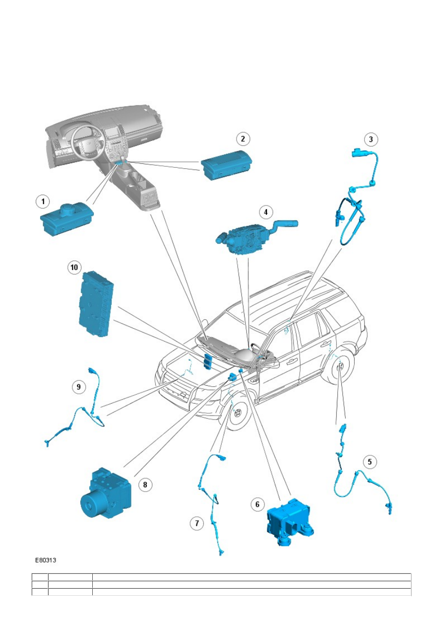
• NOTE: Left-Hand Drive (LHD) shown; Right-Hand Drive (RHD) similar.

Item Part Number

Description

1

-

Hill Descent Control (HDC) and Dynamic Stability Control (DSC) switches (with Terrain Response™)

2

-

HDC and DSC switches (without Terrain Response™)

3

-

Right-Hand (RH) rear wheel speed sensor

4

-

Steering wheel module (including steering angle sensor)

5

-

Left-Hand (LH) rear wheel speed sensor

6

-

Sensor cluster

7

-

LH front wheel speed sensor

8

-

Integrated Anti-lock Brake System (ABS) module and Hydraulic Control Unit (HCU)

9

-

RH front wheel speed sensor

10

-

Central Junction Box (CJB)

OVERVIEW

The vehicle ABS and stability control system features a Continental Teves Mk25E1 module, with an integral 4-channel HCU.
The integrated ABS module and HCU is located on the rear LH side of the engine compartment, and is installed in the
brake hydraulic circuit between the brake master cylinder and the 4 brake calipers.

The ABS module is connected to the high speed Controller Area Network (CAN) bus, and actively interacts with other
vehicle system control modules and associated sensors to receive and transmit current vehicle operating information.

When required, the ABS module will actively intervene and operate the HCU during braking or vehicle maneuvers to correct
the vehicle attitude, stability, traction or speed. During severe incidents of vehicle correction, the ABS module will also
request the Engine Control Module (ECM) to reduce engine power in order to further stabilize and correct the vehicle.

To provide full system functionality, the ABS and DSC systems comprise the following components:

DSC switch
HDC switch
4 wheel speed sensors
Sensor cluster
Steering angle sensor
Instrument cluster indicator lamps
Integrated ABS module and HCU.

The ABS system also provides brake functions that are designed to assist the vehicle or aid the driver. The following
functions are detailed in the section 'Principles of Operation':

Anti-lock Brake System (ABS)
Corner Brake Control (CBC)
Dynamic Stability Control (DSC)
Electronic Brake Force Distribution (EBD)
Electronic Traction Control (ETC)
Emergency Brake Assist (EBA)
Engine Drag-Torque Control (EDC)
HDC (with gradient release control)
Roll Stability Control (RSC)
Terrain Response™ system integration.

All the brake functions listed, apart from HDC, are automatically active when the ignition is in power mode 6 (ignition) and
the engine is running.

DYNAMIC STABILITY CONTROL SWITCH

The DSC switch allows the DSC function to be selected off. The DSC switch is non-latching and is installed in the floor
console, forward of the gear selector lever. Pressing the DSC switch connects an ignition power feed to the ABS module.
With the first press of the DSC switch, the ABS module disables the DSC functions. W hen the DSC switch is pressed again,
the ABS module re-enables the DSC functions. The DSC switch must be pressed for a minimum of 0.3 second for the ABS
module to react. The DSC function is re-enabled at the beginning of each ignition cycle.

To confirm that the DSC function is selected off, the amber colored DSC warning indicator lamp located in the instrument
cluster, is continuously illuminated. On vehicles installed with a high-line instrument cluster, a message is also displayed
in the message center to confirm that DSC is selected off.

For additional information, refer to:

Instrument Cluster

 (413-01 Instrument Cluster, Description and Operation),

Information and Message Center

 (413-08 Information and Message Center, Description and Operation).

When the DSC function is selected on, the DSC warning indicator lamp is extinguished.

Although Land Rover recommend that DSC is selected on for all normal driving conditions, it may be beneficial to de-select
DSC in order to maximize traction under the following conditions:

To rock the vehicle out of a hollow or a soft surface.
When driving on loose surfaces or with snow chains installed.
When driving in deep sand, snow or mud.
When driving on tracks with deep longitudinal ruts.

Even when DSC is deselected, driving maneuvers with extreme yaw or lateral acceleration may trigger RSC activity to
assist the vehicle stability.

To prevent mis-use of, or in the event of a broken DSC switch, a Diagnostic Trouble Code (DTC) is stored in the ABS
module memory if the input from the DSC switch is held high for more than 1 minute.

HILL DESCENT CONTROL SWITCH

The HDC switch controls the selection of the HDC function.

The HDC switch is non-latching and is installed in the floor console, forward of the gear selector lever. Momentarily
pressing and releasing the HDC switch connects an ignition power feed to the ABS module. W ith the first press and release
of the HDC switch, the ABS module enables operation of the HDC function. When the HDC switch is pressed and released
again, the ABS module disables operation of the HDC function.

To prevent mis-use of, or in the event of a broken HDC switch, if the switch is pressed for more than 10 seconds no
change of state occurs. A DTC is stored in the ABS module memory if the input from the HDC switch is held high for more
than 1 minute.

HDC Activating Stoplamps

Operation of the vehicle stoplamps during HDC is controlled by the CJB. The ABS module monitors the brake system
hydraulic pressure and requests the CJB, via the high speed CAN bus, to energize the stoplamps during active braking.

A pressure threshold and time filter prevents the stoplamps from flickering while HDC is braking.

Stop/Start Vehicles - From 2010 MY

Activation of Hill Descent Control will deactivate the Stop/Start system. However, if Hill Descent Control is activated when
the engine is shutdown in a Stop/Start cycle the engine will automatically restart. If during this event the Stop/Start
system cannot detect the driver's occupancy, for example either the driver’s safety belt or door is unlatched, the engine
will not restart. The Stop/Start system will request the driver to depress the clutch to restart the engine. The driver will be
informed of this by ‘RESTART REQUIRED PRESS CLUTCH’ being displayed in the message center.

The driver must respond to this request within a limited time period, or otherwise a conventional engine restart using the
ignition switch will be required.
For additional information, refer to: 

Starting System

 (303-06C Starting System - TD4 2.2L Diesel, Vehicles Built From:

01-03-2009, Description and Operation).

WHEEL SPEED SENSORS

Item

Part Number

Description

1

-

Retaining screw

2

-

Wheel speed sensor

3

-

Bearing seal and magnetic encoder ring

4

-

Wheel bearing

5

-

Wheel hub

An active wheel speed sensor is installed in each wheel knuckle, and provides the ABS module with a rotational speed
signal from each road wheel. The head of each wheel speed sensor is positioned close to a magnetic encoder incorporated
into the seal of the wheel bearing. Each front axle bearing encoder contains 44 north and south poles; each rear axle
bearing encoder contains 48 pole pairs. A fly lead connects each sensor to the vehicle harness.

The wheel speed sensor is supplied with a power supply and a signal connection from the ABS module. W hen the ignition
switch is in power mode 6 (ignition), the ABS module supplies power to the wheel speed sensors and monitors the return
signals. Rotation of the wheels induces current fluctuations in the speed sensor return signals. The ABS module
subsequently converts the return signals into individual wheel speeds, and the overall vehicle speed.

The ABS module outputs the individual wheel speeds, and vehicle speed on the high speed CAN bus for use by other
systems. The quality of the vehicle speed signal is also broadcast on the high speed CAN bus. If all wheel speed signals
are available to calculate vehicle speed from, the quality of the vehicle speed signal is set to 'data calculated within
specified accuracy'. If one or more wheel speed sensors are inoperative, the quality of the vehicle speed signal is set to
'accuracy outside specification'.

The ABS module monitors the wheel speed sensor circuits for faults. If a fault is detected the ABS module stores a related
DTC in memory and illuminates the appropriate warning indicator lamps, depending on the system functions affected
(DSC/ETC, ABS, EBA/EBD, HDC). A warning chime is also sounded to alert the driver to the fault condition.

For vehicles installed with a high-line instrument cluster, a message is displayed in the message center, only if the fault
affects the HDC function.


Content   ..  126  127  128  129   ..