Frelander 2. Manual - part 129


  Index      Land Rover     Land Rover Frelander 2 - service repair manual 2006-2010 year


Search            


Content   ..  127  128  129  130   ..


Frelander 2. Manual - part 129


For additional information, refer to:

Instrument Cluster

 (413-01 Instrument Cluster, Description and Operation),

Information and Message Center

 (413-08 Information and Message Center, Description and Operation).

As the wheel speed sensors are active devices, a return signal is available when the road wheels are not rotating. This
enables the ABS module to check the condition of the speed sensors while the vehicle is stationary.
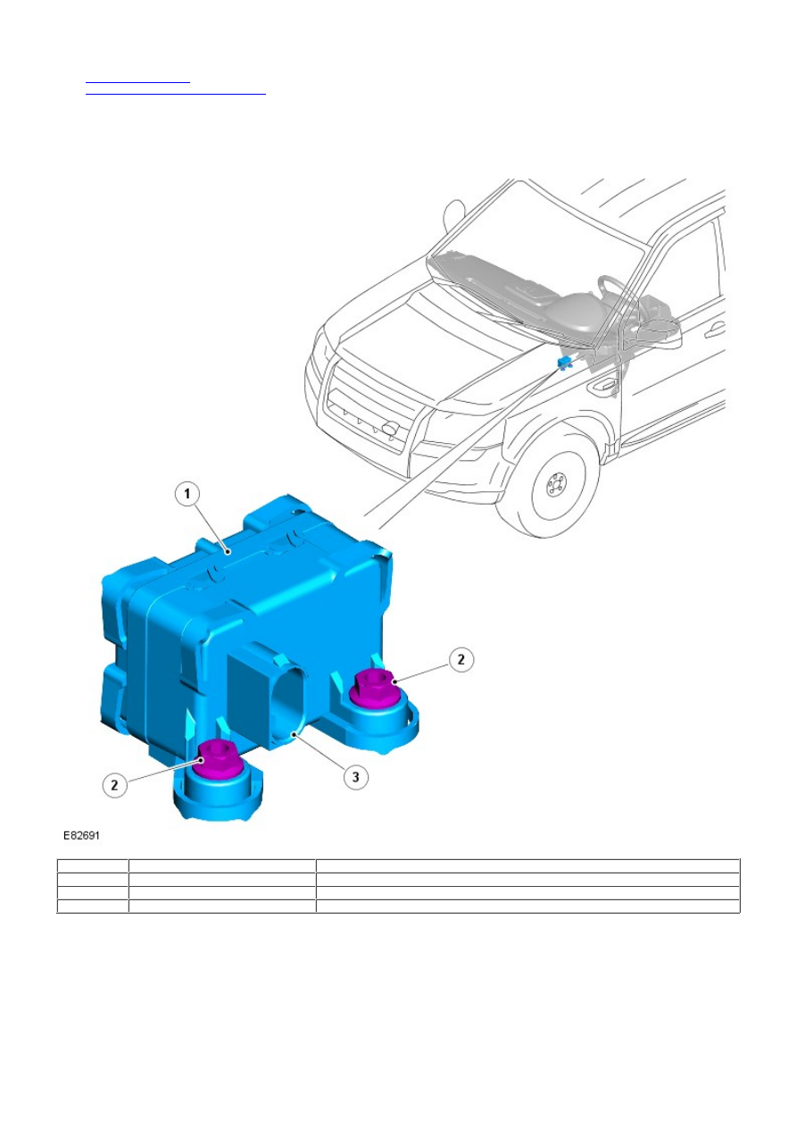
SENSOR CLUSTER

Item

Part Number

Description

1

-

Sensor cluster

2

-

Retaining stud and nut (2 off)

3

-

Electrical connector

The sensor cluster is installed beneath the center console and is secured to the transmission tunnel with 2 studs and nuts.
The sensor cluster is a compact unit that provides the ABS module with inputs of yaw rate, roll rate, longitudinal and
lateral acceleration. The ABS module broadcasts the input values on the high speed CAN bus for use by other systems.

When the ignition is in power mode 6 (ignition), the sensor cluster receives an ignition power feed from the ABS module.
The sensor cluster is also connected to the ABS module via a private CAN bus.

The sensor cluster is diagnosed by the ABS module. If a sensor fault is detected the ABS module stores a related DTC in
memory and illuminates the appropriate warning indicator lamps, depending on the system functions affected (DSC/ETC,
ABS, EBA/EBD, HDC). A warning chime is also sounded to alert the driver to the fault condition.

For vehicles installed with a high-line instrument cluster, a message is displayed in the message center, only if the fault
affects the HDC function.

For additional information, refer to:

Instrument Cluster

 (413-01 Instrument Cluster, Description and Operation),

Information and Message Center

 (413-08 Information and Message Center, Description and Operation).

STEERING WHEEL MODULE

Item

Part Number

Description

1

-

Steering wheel module

2

-

Clockspring and steering angle sensor

The steering wheel module contains the steering angle sensor, clockspring and steering column multifunction switches to
form an integral component. The steering angle sensor is connected directly to the clockspring.

The steering wheel module is mounted to the upper steering column with 2 screws, and receives an electrical supply from
the main harness via a 4-pin connector located on the side of the unit. The module provides the location and electrical
connection for the 2 multifunction switches.

Input signals from the steering angle sensor are received and processed by the steering wheel module to calculate the
steering wheel angle, and steering wheel angle speed. The information is transmitted on the high speed CAN bus for use
by the ABS module.

Steering Angle Sensor

The steering angle sensor is connected to the steering wheel with 2 dowels. The steering angle sensor monitors steering
wheel rotation, and provides information of the steering wheel angle and rate of speed of steering wheel movements.

A code wheel and 16 optical digital sensors are installed inside the steering wheel angle sensor. Rotation of the code

wheel is read by the optical-digital sensors to produce steering wheel rotational speed signals. The steering angle sensor
is able to measure a rotation range of +/- 720 degrees, although the steering mechanism will only allow the steering
wheel to rotate a maximum of +/-540 degrees.

Signals from the steering angle sensor are transmitted on the vehicle high speed CAN bus, and received and processed by
other systems such as DSC. The transmitted information includes details of steering wheel angle and steering wheel
rotational speed, along with signal integrity information.

If a fault occurs within the steering angle sensor, a DTC will be set and stored in the steering angle sensor memory. The
steering angle sensor fault is also stored in the ABS module memory that illuminates the appropriate warning indicator
lamps, depending on the system functions affected (DSC/ETC, ABS, EBA/EBD, HDC). A warning chime is also sounded to
alert the driver to the fault condition.

For vehicles installed with a high-line instrument cluster, a message is displayed in the message center, only if the fault
affects the HDC function.

For additional information, refer to:

Instrument Cluster

 (413-01 Instrument Cluster, Description and Operation),

Information and Message Center

 (413-08 Information and Message Center, Description and Operation).

The steering angle sensor and ABS module are able to be interrogated using the Land Rover approved diagnostic
equipment.

Clockspring

The clockspring is a rotary coupling that provides the electrical connection between the fixed steering wheel module, and
the steering wheel mounted controls and Supplemental Restraint System (SRS) driver's airbag.

A colored indicator is provided within the clockspring and is visible through a transparent perspex cover when the steering
wheel is removed, and the steering angle sensor is aligned to the central position. The indicator makes sure the steering
angle sensor and steering system are correctly aligned following repairs to the steering mechanism.

Service Information

Before separating the steering components from the connecting steering column, the clockspring must be aligned to the
center position (indicator visible) and the wheels pointing straight ahead. The clockspring is retained in the central
position with a locking screw.

INSTRUMENT CLUSTER INDICATOR LAMPS

Item

Part Number

Description

1

-

Brake warning indicator lamp – all except North American Specification (NAS)

2

-

ABS warning indicator lamp

3

-

Brake warning indicator lamp - NAS vehicles

4

-

HDC warning indicator lamp (low line instrument cluster)

5

-

DSC warning indicator lamp

6

-

HDC information indicator lamp

The instrument cluster contains 2 types of indicator lamps to display the operating status of the selected anti-lock control
- stability assist functions. The indicator lamps provide a visual notification of either a system warning or information
indication to the driver. There are 4 indicator lamps on vehicles with a high-line instrument cluster; 5 indicator lamps on
vehicles with a low-line instrument cluster.

The following anti-lock control - stability assist indicator lamps are installed in the instrument cluster:

ABS warning indicator lamp
Brake warning indicator lamp
DSC warning indicator lamp
HDC warning indicator lamp
HDC information indicator lamp.

For additional information, refer to: 

Instrument Cluster

 (413-01 Instrument Cluster, Description and Operation).

ANTI-LOCK BRAKE SYSTEM MODULE

The ABS module controls the brake functions by operating the HCU to modulate hydraulic pressure to the individual wheel
brakes.


Content   ..  127  128  129  130   ..