Land Rover Discovery. Manual - part 168


  Index      Land Rover     Land Rover Discovery - service 1995-1996 year


Search            


Content   ..  166  167  168  169   ..


Land Rover Discovery. Manual - part 168


76

CHASSIS AND BODY

4

REPAIR

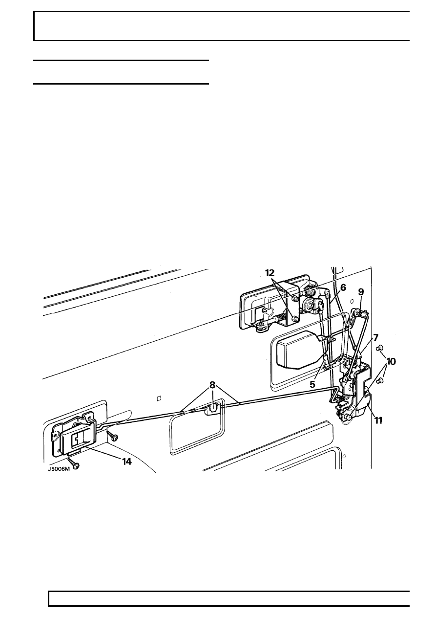
FRONT DOOR LOCK, OUTSIDE AND INSIDE
DOOR RELEASE HANDLES

Service repair no - 76.37.12/31

Remove

1. Disconnect battery negative lead.
2. Remove the door trim panel.

See front door

trim panel.

3. Remove the door glass and regulator.

See

front door glass and regulator.

4. Where applicable remove the door actuator unit.

See ELECTRICAL, Repair, front door
actuator unit.

5. Disconnect the lock barrel control rod from the

lock by releasing the metal clip at the bottom of
the rod.

6. Disconnect the control rod from the outside door

release handle by pulling it out of the plastic
ferrule.

7. Disconnect the remote button control rod from

the lock by releasing the metal clip at the bottom
of the rod and withdraw the rod from the door.

8. Disconnect the control rod connector between

the inside door release handle and the door lock
by releasing the metal clip and pulling one of the
control rods out of the plastic connecting block.
This is accessible through the small centre
cut-out in the door panel. The control rod also
passes through a guide bracket in the inside of
the inner door panel.

9. From inside the door panel push out the small

pin that secures the quadrant to the inner door
panel. Push the quadrant out of the panel.

10. Release the door lock by removing the two

counter-sunk screws from the door edge and the
single screw and shakeproof washer on the
inner door panel.

CHASSIS AND BODY

5

REPAIR

11. Withdraw the lock through the lower rear cut-out

on the inner door panel.

12. Remove the two nuts, shakeproof washers and

retaining bracket securing the outer door release
handle to the outer door panel, accessible
through the upper rear cut-out on the inner door
panel.

13. Carefully detach the door release handle from

the outer panel.

14. Remove the two screws securing the inside door

release handle to the inner panel.

15. Withdraw the handle from its location with the

connecting rod half still attached.

16. Unclip the end of the connecting rod from the

handle.

Refit

17. Reverse removal procedure.

76

CHASSIS AND BODY

6

REPAIR

ADJUSTMENT-FRONT DOOR LOCK AND HANDLE
ASSEMBLY

Service repair no - 76.37.47

Inside door release handle to lock

1. Refit the inside door release handle surround

before any adjustment is made, allowing the
handle to be set from the correct operating
position.

2. At the lock end of the interior handle connecting

rod, rotate the spring tensioned nyloc nut
clockwise or counter-clockwise, as necessary to
shorten or extend the operating length of the rod.

Outside door release handle to lock

3. Disconnect the connecting rod from the plastic

ferrule at the rear of the outer door release
handle. Rotate the rod clockwise or
counter-clockwise to shorten or extend the
operating length as necessary.

NOTE: Door release should be effective
before the total handle movement is
exhausted to provide a small overthrow

movement.

CHASSIS AND BODY

7

REPAIR

REAR SIDE DOORS

Service repair no - 76.28.02

Remove

1. Disconnect battery negative lead.
2. Detach the convoluted grommet from the ’B’

post.

3. Withdraw the door harness multiplugs from the

’B’ post and disconnect them.

4. Remove the bolts and washers securing the

check strap to the ’B’ post.

WARNING: Instruction 5 MUST BE carried
out with assistance.

5. Remove the door hinge ’C’ clips from the hinge

posts and with assistance carefully lift the door
from the vehicle.

Refit

6. Reverse removal procedure. Fitting new ’C’ clips

if the existing ones are worn or distorted.

7. Check the operation of the door and lock. If

necessary, adjust the door and striker.

Adjust

8. Adjust the door by adding or removing shims

between the hinge and the door to move the
door forward or rearward in the opening.

9. To adjust the door up, down or in and out of the

opening, loosen the screws securing the hinges
to the door, adjust as necessary and retighten
the screws to the correct torque value.

10. Adjustment of the door striker is identical to the

procedure for front doors.

NOTE: If it is necessary to remove the
hinges from the ’B’ post they must be
refitted in exactly the same position, using

an equal thickness of shims to those removed.


Content   ..  166  167  168  169   ..